Image forming apparatus
- Summary
- Abstract
- Description
- Claims
- Application Information
AI Technical Summary
Benefits of technology
Problems solved by technology
Method used
Image

Examples
first embodiment
{Construction}
[0076] The present invention will be described in detail with reference to the accompanying drawings.
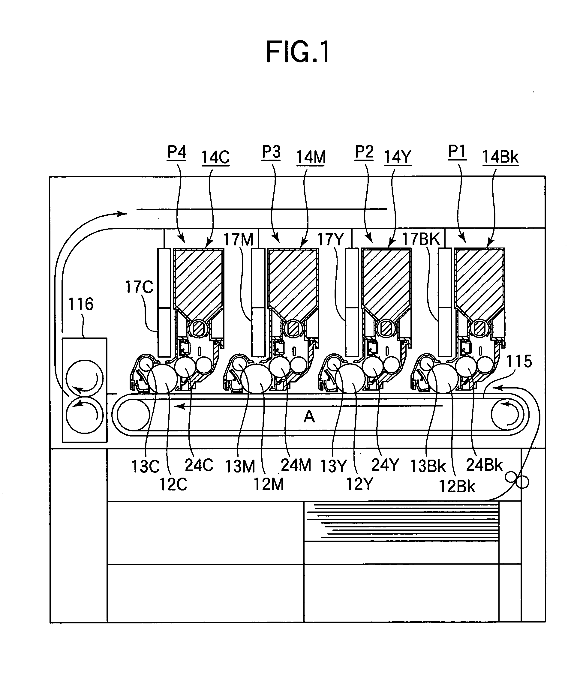
[0077]FIG. 1 is a schematic view of a printer according to a first embodiment. Referring to FIG. 1, the printer includes image-forming mechanisms P1 to P4 that form black, yellow, magenta, and cyan images, respectively. The image-forming mechanisms P1 to P4 are aligned in a direction shown by arrow A in which a transfer belt (i.e., transport belt) 115 runs.
[0078] The image-forming mechanisms P1 to P4 include image-forming units 14BK, 14Y, 14M, and 14C and LED heads 17BK, 17Y, 17M, and 17C. The transfer rollers, not shown, oppose the image-forming units 14BK, 14Y, 14M, and 14C with the transfer belt 115 sandwiched between the image-forming units and the transfer rollers.
[0079] The image-forming units 14BK, 14Y, 14M, and 14C include photoconductive drums 12BK, 12Y, 12M, and 12C, charging rollers 13Bk, 13Y, 13M, and 13C, and developing rollers 24BK, 24Y, 24M, and 24C. ...
second embodiment
[0111] Elements similar to those in the first embodiment have been given like reference numerals and the description thereof is omitted.
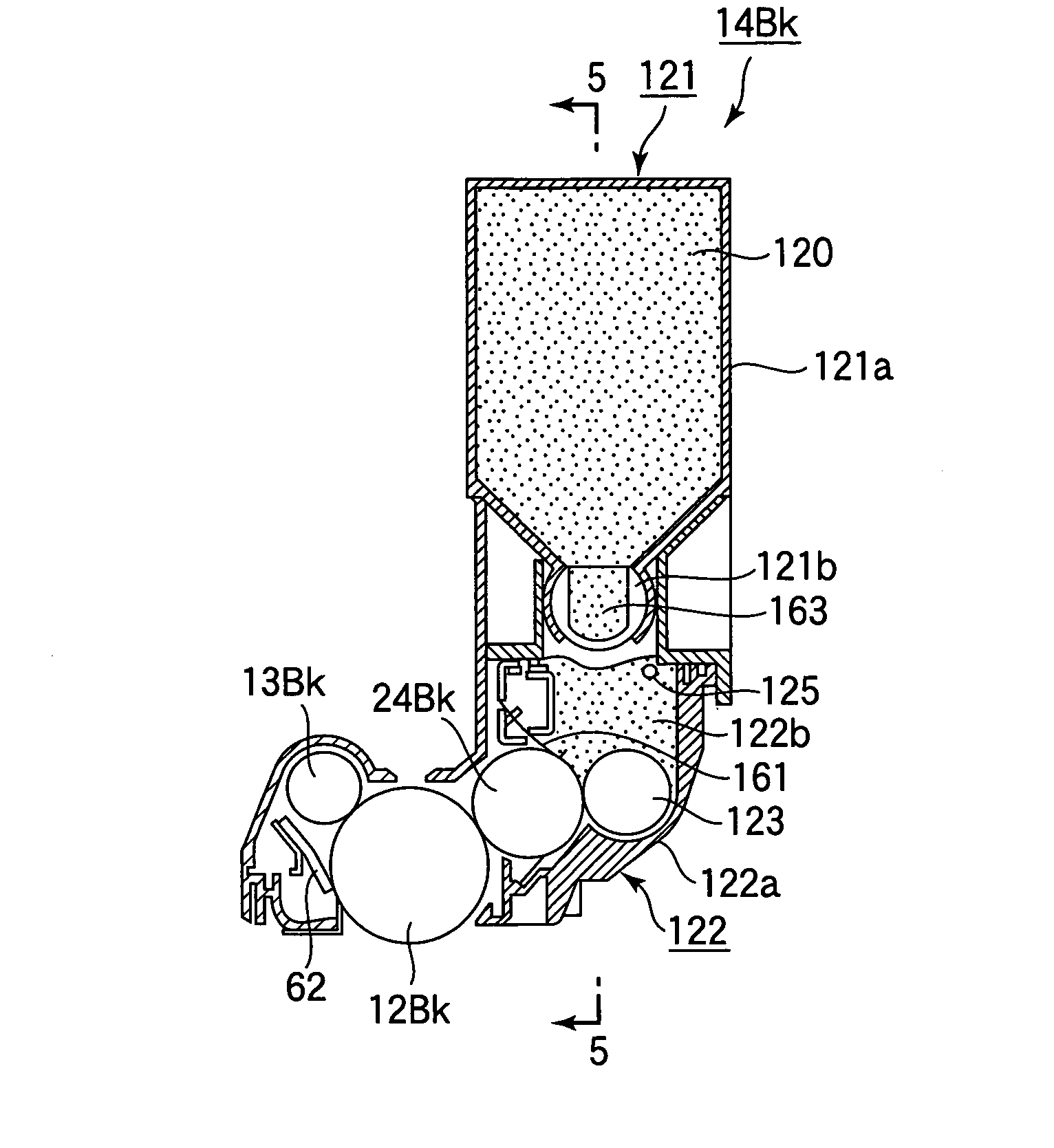
[0112]FIG. 14 is a cross-sectional view of an image-forming unit 14BK (FIG. 1) according to a second embodiment.
[0113]FIG. 15 is a cross-sectional view of the image-forming unit of FIG. 14, taken along line 15-15.
[0114] Referring to FIG. 14, each complete rotation of the valve 221b supplies a predetermined amount of toner 220 from the toner chamber 221a into the toner reservoir 222b. The toner reservoir 222b has an agitator 229 therein that rotates to agitate the toner 220. The agitator 229 is similar to an agitator 527 in FIG. 31. The agitator 229 is located in the agitation region 228 and is rotatably supported. The agitator 229 extends in a longitudinal direction parallel to the rotational axes of a photoconductive drum 12BK (FIG. 1) a developing roller 24BK (FIG. 1), and a toner supplying roller 223.
[0115] There are provided a first sensor 2...
third embodiment
[0131]FIG. 20 is a cross-sectional view of an ID unit (Image Drum Unit) 320 when printing is performed at a low print duty.
[0132] Referring to FIG. 20, a process cartridge 312 has a toner reservoir 382. A toner cartridge 311 has a toner chamber 383 and is detachably mounted to the process cartridge 312. The toner cartridge 311 and the process cartridge 312 form the ID unit 320. The toner cartridge 311 holds toner 313 therein. A transport spiral 314 is rotatably supported in the toner cartridge 311 and is of the same configuration as a transport spiral 514 in FIG. 31. The transport spiral 314 rotates in a direction shown by arrow D to transport the toner 313 toward the middle of the toner cartridge 311. The toner 313 is transported into the process cartridge 312 through a toner outlet 315 formed in the middle of the toner cartridge 311. A shutter 311a is disposed at the bottom of the toner cartridge 311. The shutter 311a remains closed until the toner cartridge 311 has been attached...
PUM
 Abstract
Description
Claims
Application Information
 - R&D
- Intellectual Property
- Life Sciences
- Materials
- Tech Scout
- Unparalleled Data Quality
- Higher Quality Content
- 60% Fewer Hallucinations
Browse by: Latest US Patents, China's latest patents, Technical Efficacy Thesaurus, Application Domain, Technology Topic, Popular Technical Reports.
© 2025 PatSnap. All rights reserved.Legal|Privacy policy|Modern Slavery Act Transparency Statement|Sitemap|About US| Contact US: help@patsnap.com