Low friction rotary knife

a rotary knife and low friction technology, applied in the field of power operated rotary knives, can solve the problems of blade shifting axially into undesired contact with the blade housing, other problems, and inability to operate, so as to reduce the friction between blade and housing

Inactive Publication Date: 2005-06-16
BETTCHER INDUSTRIES
View PDF26 Cites 36 Cited by
  • Summary
  • Abstract
  • Description
  • Claims
  • Application Information

AI Technical Summary

Benefits of technology

[0012] In the preferred knife the blade supporting structure comprises a split blade housing member that is radially expandable and contractible to receive the blade. The housing member is provided with bead sections that are spaced circumferentially apart about the blade periphery, project into a bearing race formed in the blade, and engage the blade bearing faces as the knife operates. The split blade housing member is adjusted so the blade and housing engage along relatively short lines of bearing contact that serve to minimize blade—housing friction—and consequential blade and housing...

Problems solved by technology

Some prior art rotary knives tended to vibrate undesirably in use because the blade rotation axis was permitted to shift relative to the blade housing.
In the knives where the blade was secured to the knife by confronting wedging surfaces, the blade vibration caused the blade to shift axially into undesired contact with the blade housing.
This axial blade movement contributed both to knife vibration and blade heati...

Method used


Image

  • Low friction rotary knife
  • Low friction rotary knife
  • Low friction rotary knife

Examples


Embodiment Construction

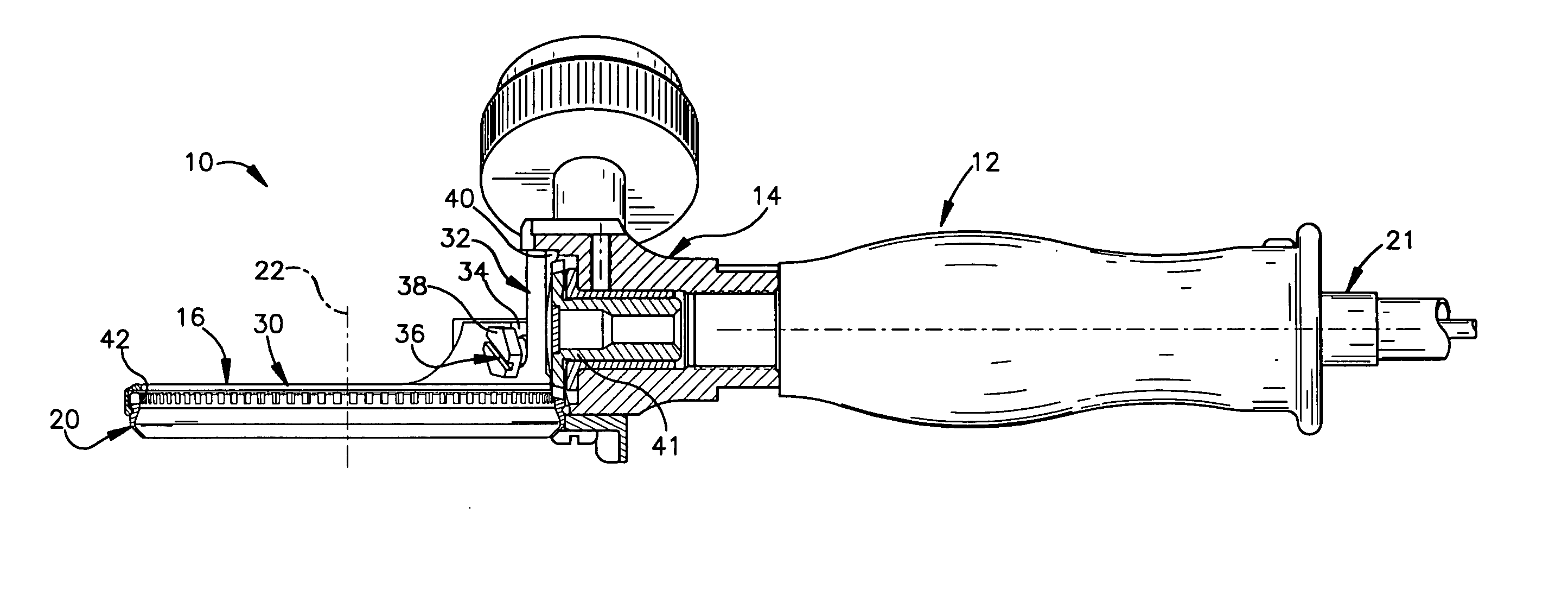
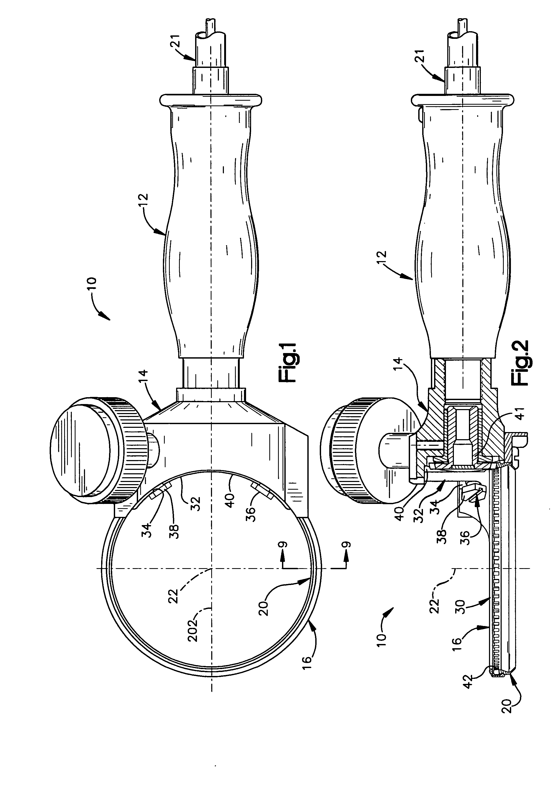
[0030] A power operated knife 10 constructed according to a preferred embodiment of the invention is illustrated by FIGS. 1 and 2 of the drawings as comprising a handle 12, a headpiece 14, a blade support structure 16 and an annular blade 20.

[0031] The knife 10 is connected to a remote electric motor via a flex shaft 21 that extends into the handle 12 and transmits drive from the motor to the blade 20. The motor and flex shaft may be of any conventional or suitable construction and are not illustrated or described in detail. The flex shaft is sufficiently supple that the user of the knife, grasping the handle, moves the knife with ease and accuracy while slicing or trimming meat, or removing meat from bones, etc. The handle 12 and headpiece 14 may be of any conventional or suitable construction and are therefore not described in detail. Although an electric motor driven knife is disclosed, the knife could as well contain a pneumatic motor in the handle 12 and be connected to a comp...


PUM


Abstract

A power operated knife comprises a blade supporting structure supporting an annular blade for rotation about a central axis. The blade and blade supporting structure are engagable along bearing contact locations that are spaced apart in a direction parallel to the axis so that the blade is stabilized both radially and axially as the knife operates. The blade supporting structure comprises a split blade housing member that is radially expandible and contractible to receive the blade. The split blade housing member and blade engage along relatively short lines of bearing contact that serve to minimize friction and blade heating when the knife operates. The bearing locations are spaced apart both circumferentially around the blade perimeter and in the direction of the axis so that the blade position is stabilized during operation of the knife.

Description

FIELD OF THE INVENTION [0001] The present invention relates to power operated rotary knives and more particularly to a power operated rotary knife wherein a rotatable annular blade is supported for rotation about a central axis by a blade support structure providing bearing contact that minimizes blade vibration and heating. BACKGROUND OF THE INVENTION [0002] Power operated rotary knives have been in wide-spread use in meat packing and other commercial food processing facilities. These knives usually comprised a handle and a blade housing that supported an annular knife blade. The knife blade was driven about its central axis relative to the blade housing by a motor via a gear train. [0003] The knife blade comprised an annular body, a blade section projecting axially from the body and driving gear teeth projecting axially from the body oppositely from the blade section. The blade housing maintained the blade in position relative to the knife as the blade rotated. The blade was subje...

Claims


Application Information

Patent Timeline
IPC IPC(8): B26B25/00B26D1/14B26D1/45
CPCB26B25/002A22B5/165A22C17/04
Inventor WHITED, JEFFREY A.
Owner BETTCHER INDUSTRIES
Why Eureka
Try Eureka