
Pivotal shaft assembly for plane displays

a technology of pivoting shaft and plane display, which is applied in the direction of machine supports, transportation and packaging, and other domestic objects, can solve the problem of not meeting the requirements of multi-directional adjustmen

Inactive Publication Date: 2005-06-16
LIN CHIN CHIH
View PDF7 Cites 64 Cited by
  • Summary
  • Abstract
  • Description
  • Claims
  • Application Information

AI Technical Summary

Problems solved by technology

However, it still cannot meet the requirements for the multi-directional adjustment.
However, if one of the lateral sides is not secured, the spherical nest device will be loosened or fallen off, resulting in undesirable effects.

Method used


Image

  • Pivotal shaft assembly for plane displays
  • Pivotal shaft assembly for plane displays
  • Pivotal shaft assembly for plane displays

Examples


Embodiment Construction

[0012] To make it easier for our examiner to understand the objective of the invention, its structure, innovative features, and performance, we use a preferred embodiment together with the attached drawings for the detailed description of the invention.

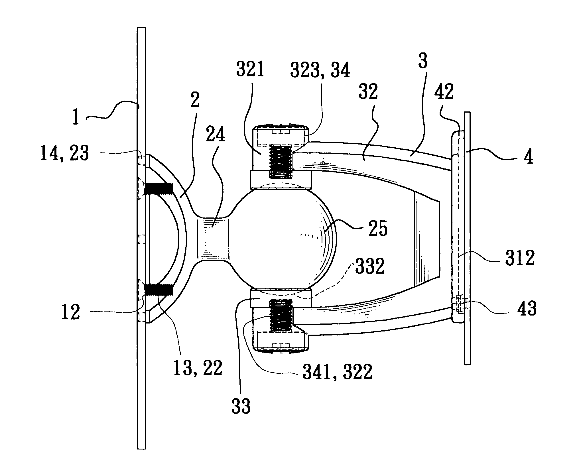
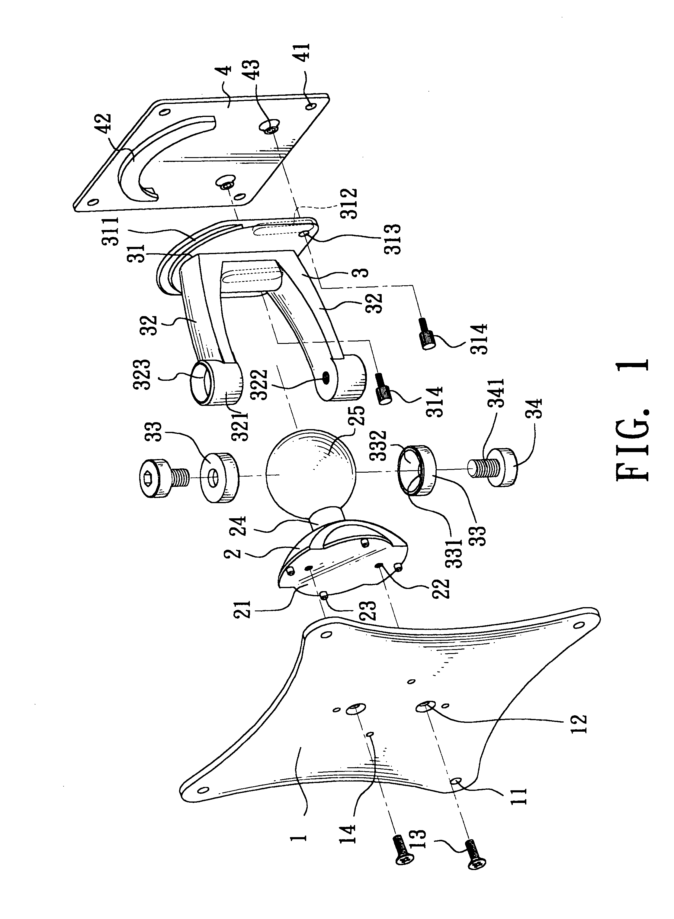
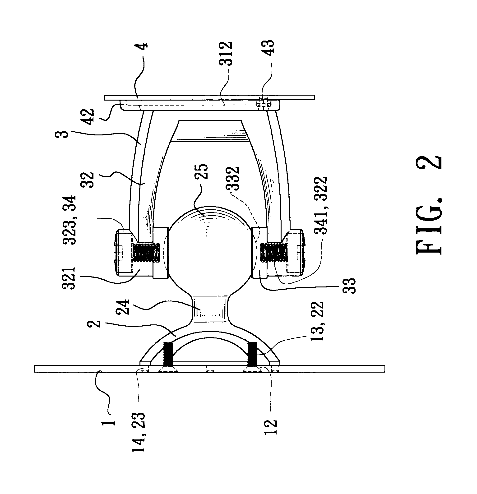
[0013] Please refer to FIGS. 1 and 2 for the pivotal shaft device according to this invention. The pivotal shaft comprises a bottom plate 1, a fixing member 2, a rotational member 3, and a connecting cover 4; wherein the bottom plate 1 is a plate having a plurality of plate holes or plate grooves 11 on its surface for passing a screw through and securing the bottom plate 1 to a fixed object such as a wall, and at least one through hole 12 at its center for passing a screw 13 through and being secured into a threaded hole 22 at the bottom of the fixing member 2. Further, a plurality of positioning holes is disposed around the through holes 12 for aligning and securing a positioning tenon at the bottom of the fixing member 2 with the p...


PUM


Abstract

The present invention discloses a pivotal shaft assembly for plane displays, including a bottom plate, a fixing member mounted at the front side of the bottom plate and having a positioning ball integrally coupled to the front side of a support base of the spherical nest device, a rotational member having two extension rods extended from the rear side of a connecting plate, each extension rod at one end having a connecting end and a corresponding axial hole thereon along its axial direction, and two inner sides of the connecting ends clamping the positioning ball by pressing on a curve groove corresponding to the curvature of the positioning ball with the inner sides, and two adjusting members of the extension rod passing through the axial hole to support a pressing ring, such that the positioning ball being clamped securely along the same axis and capable of moving along its surface to provide a multi-directional adjustment.

Description

FIELD OF THE INVENTION [0001] The present invention relates to a pivotal shaft assembly, more particularly to a pivotal shaft assembly for plane displays which allows users to make a multi-directional adjustment to the angle of elevation of the plane displays. BACKGROUND OF THE INVENTION [0002] Since a plane display such as a liquid crystal display (LCD) monitor, an LCD TV, or a plasma TV has special features of lightness, thinness, shortness, and compactness, therefore the plane display has become a mainstream of the display product and gradually replaces the traditional cathode ray tube (CRT). In general, a vertical type plane display has a pivotal shaft device between the main body and the base of the display such as a rotational shaft disposed on each of the two sides of the display to provide users an optimal viewing angle. In this way, the main body of the display can be adjusted with an inclined angle forward or backward with respect to the base. [0003] Considering the limite...

Claims


Application Information

Patent Timeline
IPC IPC(8): F16C11/06F16M11/14
CPCF16C11/06Y10S248/917F16M13/02F16M11/14
Inventor LIN, CHIN-CHIH
Owner LIN CHIN CHIH
Features
  • Generate Ideas
  • Intellectual Property
  • Life Sciences
  • Materials
  • Tech Scout
  • Unparalleled Data Quality
  • Higher Quality Content
  • 60% Fewer Hallucinations
Learn More