
Multifocal contact lens and method of manufacture thereof

Active Publication Date: 2005-06-16
BAUSCH & LOMB INC
View PDF2 Cites 110 Cited by
  • Summary
  • Abstract
  • Description
  • Claims
  • Application Information

AI Technical Summary

Benefits of technology

[0015] An advantage of the lens of the present invention is that the occurrence of simultaneous vision is reduced and improved visual quality is provided without a substantial reduction in the amount of oxygen transferred to the eye.
[0016] Another advantage of the lens of the present invention is that the occurrence of simultaneous vision is reduced and improved visual quality is provided without substantially reducing the efficiency with which the lens is flushed by tears.
[0017] Yet another advantage of the contact lens of the present invention is that the occurrence of simultaneous vision is reduced and improved visual quality is provided without requiring large steps between visual regions, thereby reducing discomfort to lens wearers.

Problems solved by technology

In effect, the wearer experiences an undesirable effect referred to as simultaneous vision in which the image appears in focus but is surrounded by an out-of-focus halo.
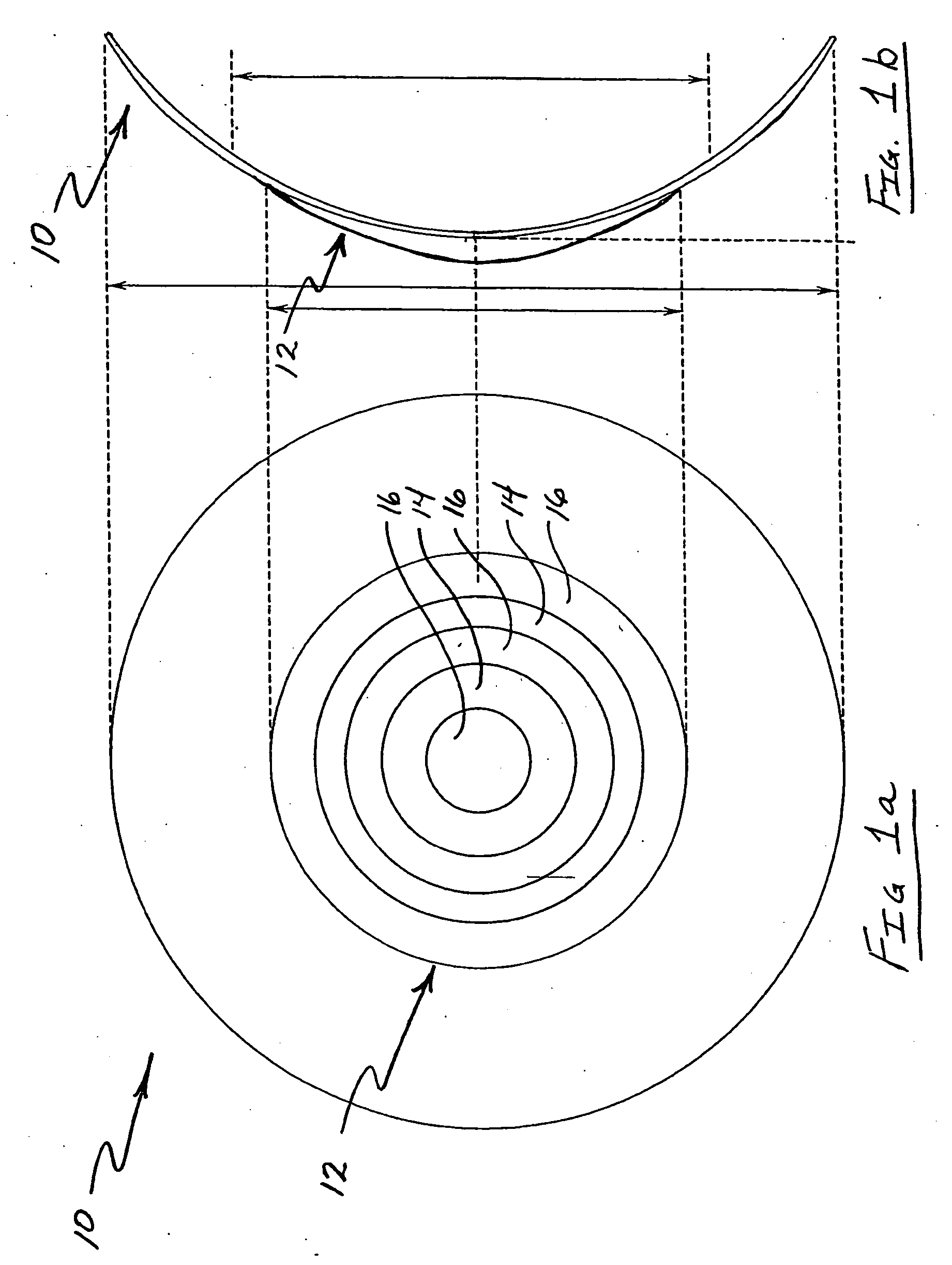
Thus, although conventional bifocal contact lens 10 is efficiently flushed with tears, the wearer may experience undesirable simultaneous vision.
Ballasting techniques reduce the efficiency with which a lens is flushed.
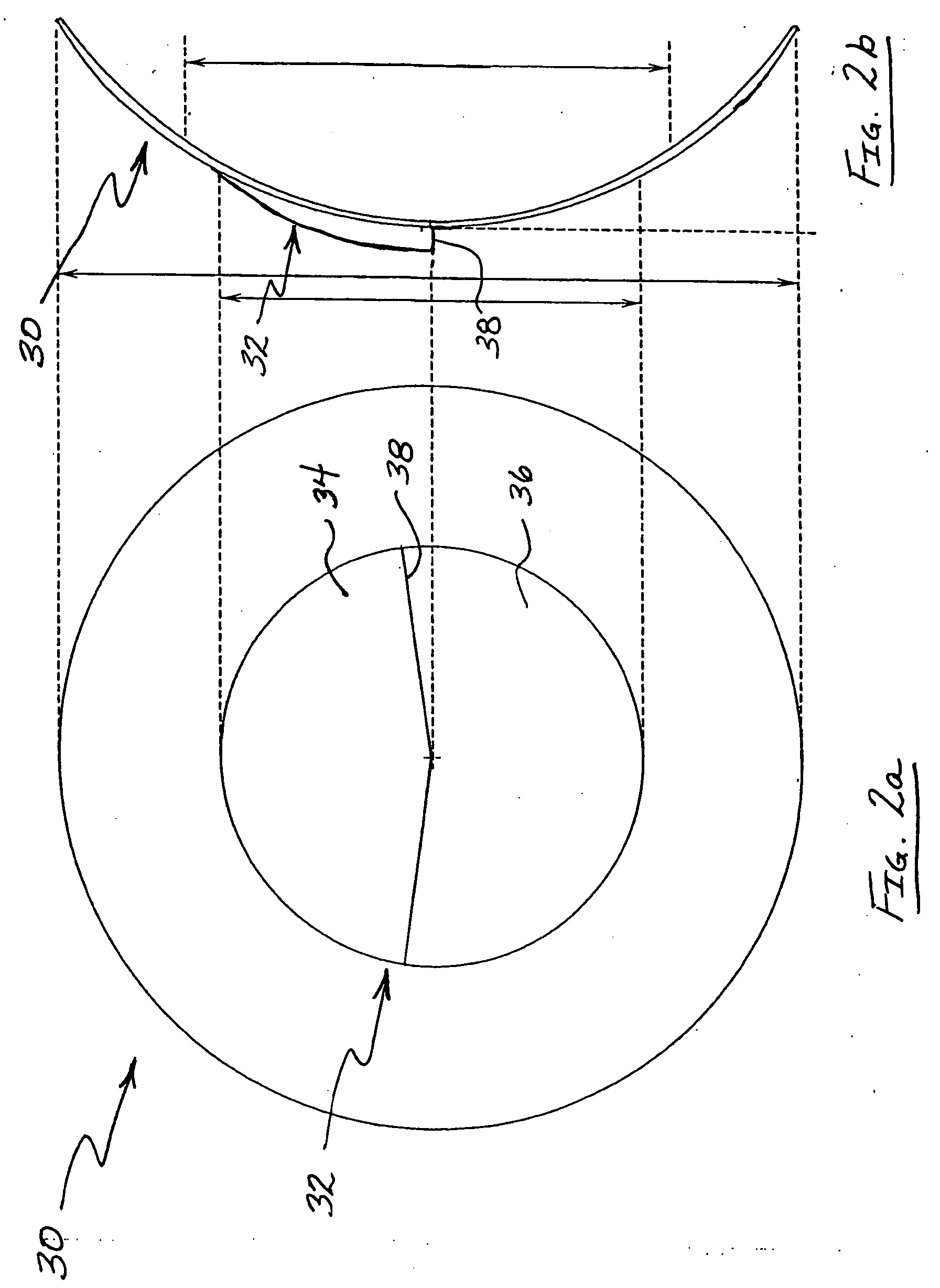
The extra thickness of these lenses and the required ballasting techniques reduce the oxygen transfer to the surface of the eye and could lead to an increased risk of corneal edema.
Thus, although reducing simultaneous vision and providing better visual quality than simultaneous bifocal contact lens 10, translating bifocal contact lens 30 reduces oxygen transfer to the eye, is flushed less efficiently, and may be uncomfortable to some wearers.

Method used


Image

  • Multifocal contact lens and method of manufacture thereof
  • Multifocal contact lens and method of manufacture thereof
  • Multifocal contact lens and method of manufacture thereof

Examples


Embodiment Construction

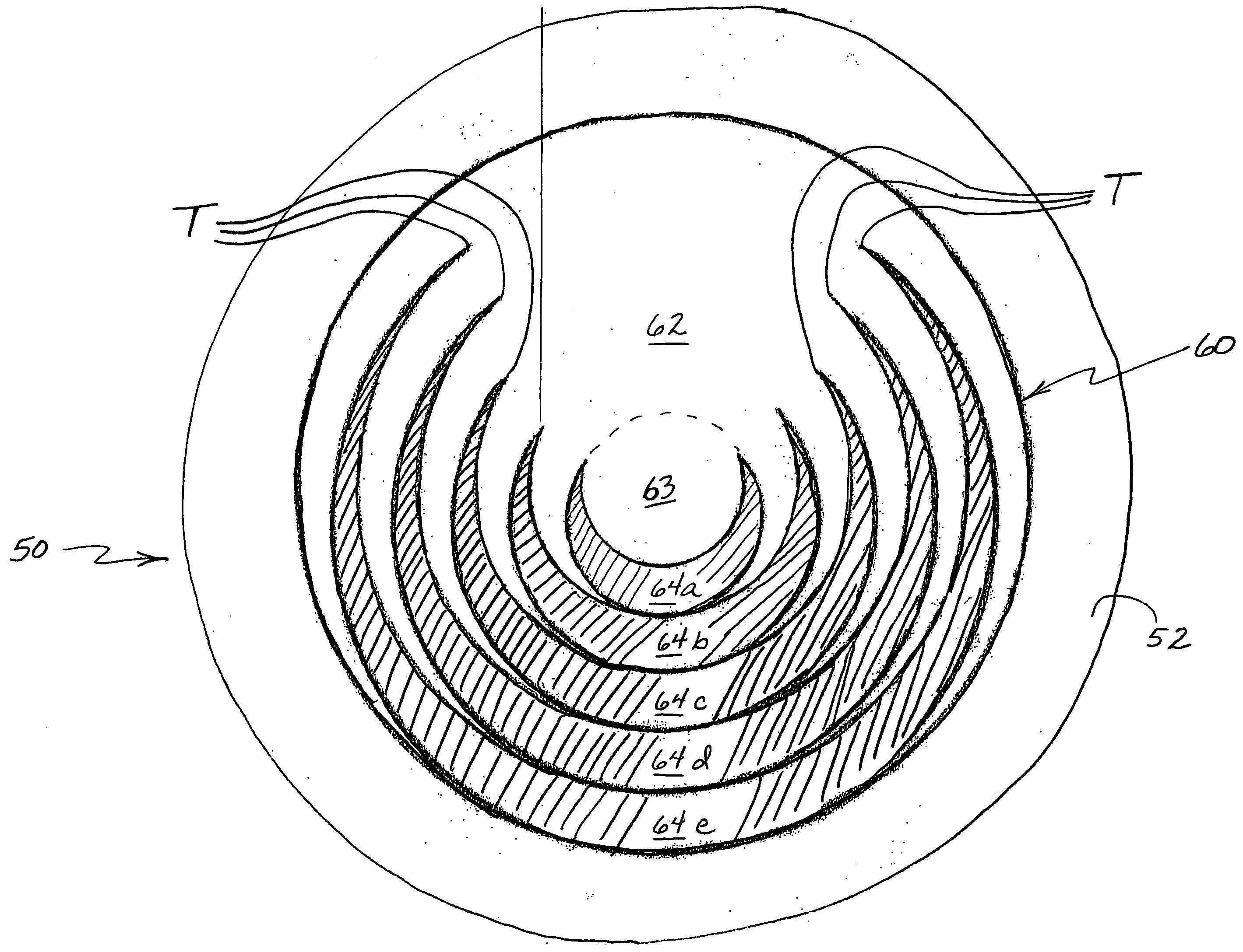
[0026] Referring now to FIGS. 3 and 4, one embodiment of a contact lens of the present invention is shown. As best shown in FIG. 4, lens 50 includes an anterior surface 52 and a posterior surface 54. Anterior surface 52 includes an optical zone 60 formed therein according to a method to be hereinafter described, and posterior surface 54 is formed to conform to the cornea of a wearer in known fashion.

[0027] Optical zone 60 includes first region 62, central zone 63 and secondary regions 64a, 64b, 64c, 64d, 64e. For each region, the optical curve is a sphere. First region 62 is primarily disposed in the superior region of optical zone 60, and secondary regions 64a-e are disposed primarily in the inferior region of optical zone 60. Secondary regions 64a-e are substantially concentric relative to each other. Generally, lens 50 is designed for distance viewing by configuring first region 62 as a distance viewing region. Secondary regions 64a-e may be configured as near or intermediate vi...


PUM


Abstract

An optical zone for a lens has a center optical axis. A first region of the optical zone includes a first optical curve having a first optical axis that is collinear with the center optical axis. A plurality of secondary regions is formed within the first region. Each of the secondary regions has a respective secondary optical curve with a corresponding secondary optical axis. Each secondary optical axis is collinear with the first optical axis. Each of the secondary optical curves is decentered relative to the first optical curve.

Description

FIELD OF THE INVENTION [0001] The present invention relates to contact lenses. More particularly, the present invention relates to a contact lens that combines the desirable characteristics of simultaneous and translating bifocal and / or multifocal lenses, and a method of manufacturing such a lens. BACKGROUND OF THE INVENTION [0002]FIG. 1 (not drawn to scale) shows an exemplary conventional bifocal contact lens 10 having an optical zone 12. Optical zone 12 is comprised of concentric zones of alternating near viewing regions 14 and distance viewing regions 16. When viewing a distant image through optical zone 12, the image appears focused and clear when viewed through distance regions 16 but out of focus when viewed though near regions 14. A similar effect occurs when viewing a near object. In effect, the wearer experiences an undesirable effect referred to as simultaneous vision in which the image appears in focus but is surrounded by an out-of-focus halo. [0003] Near viewing regions...

Claims


Application Information

Patent Timeline
IPC IPC(8): G02C7/04
CPCG02C7/042
Inventor ALTMANN, GRIFFITH E.
Owner BAUSCH & LOMB INC
Learn More