
Workout apparatus

a workout device and portable technology, applied in sport apparatus, gymnastic exercise, gymnastic climbing, etc., can solve the problems of complex and expensive, difficult to store,

Inactive Publication Date: 2005-06-16
LOPEZ LEONARD P
View PDF3 Cites 51 Cited by
  • Summary
  • Abstract
  • Description
  • Claims
  • Application Information

AI Technical Summary

Benefits of technology

[0004] The present invention disclosed and claimed herein, in one aspect thereof, comprises a workout apparatus. The apparatus includes a crossbar member, a first pivot device disposed on a first end of the crossbar member, and a second pivot device disposed on a second end of the crossbar member. A first set of support legs is provided that comprises a first downwardly extending leg with one end thereof disposed in the first pivot device and pivotable therein and a second downwardly extending leg having a first end pivotably engaged with the first pivot device. The first and second downwardly extending legs are operable to pivot from a substantially parallel relationship to each other to a non-parallel relationship in a diverging form. A restraining device is provided for restraining the first and second downwardly extending legs from diverging beyond a predetermined point. A second set of support legs is provided that comprises a third downwardly extending leg with one end thereof disposed in the second pivot device and pivotable therein and a fourth downwardly extending leg having a second end pivotably engaged with the second pivot device. The third and fourth downwardly extending legs are operable to pivot from a substantially parallel relationship to each other to a non-parallel relationship in a diverging manner. A restraining device i

Problems solved by technology

However, due to the expense of health clubs, a large number of individuals desire to have the workout equipment in their home.
However, they are complex and expensive and difficult to store.

Method used


Image

  • Workout apparatus
  • Workout apparatus
  • Workout apparatus

Examples


Embodiment Construction

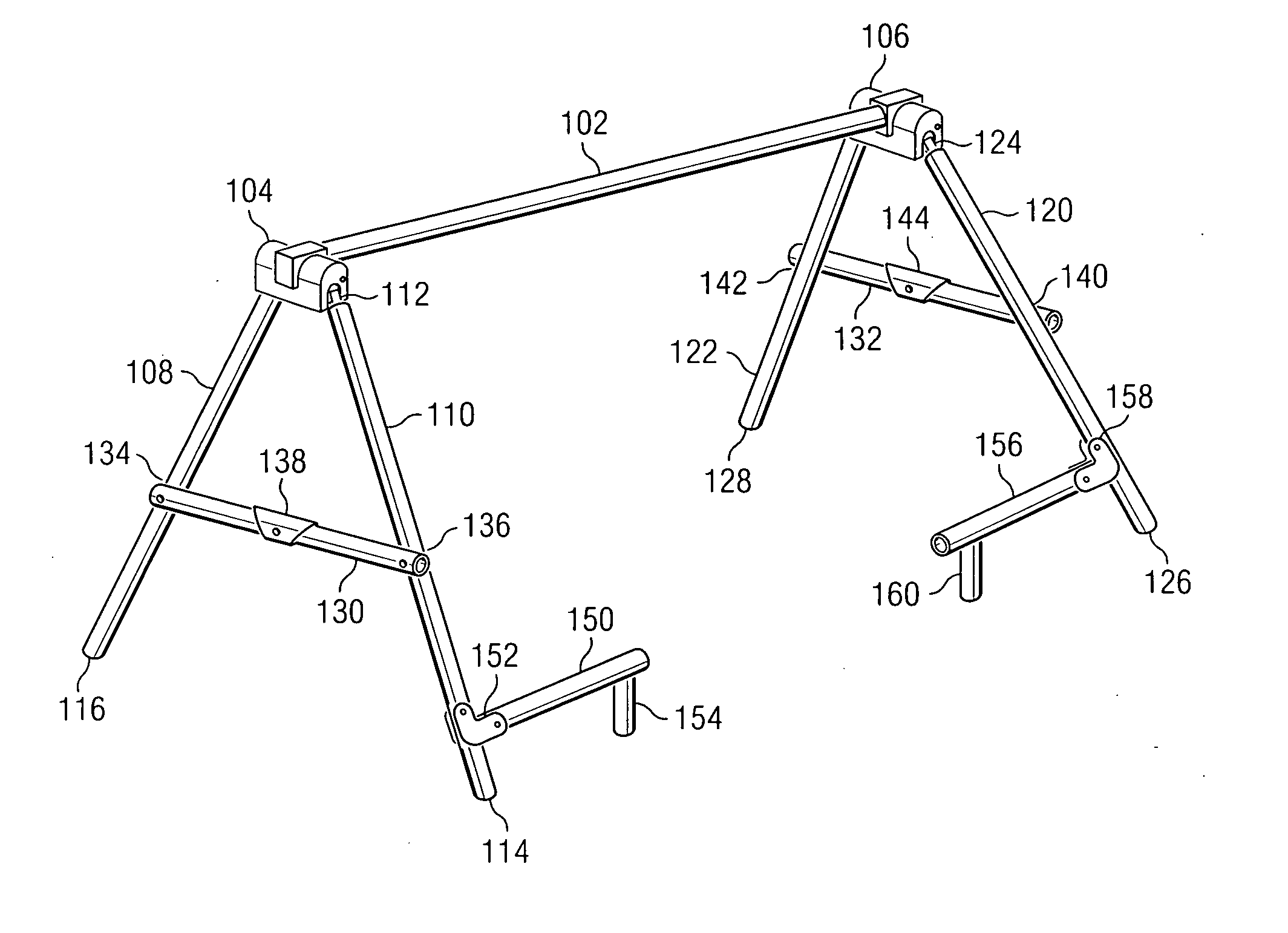
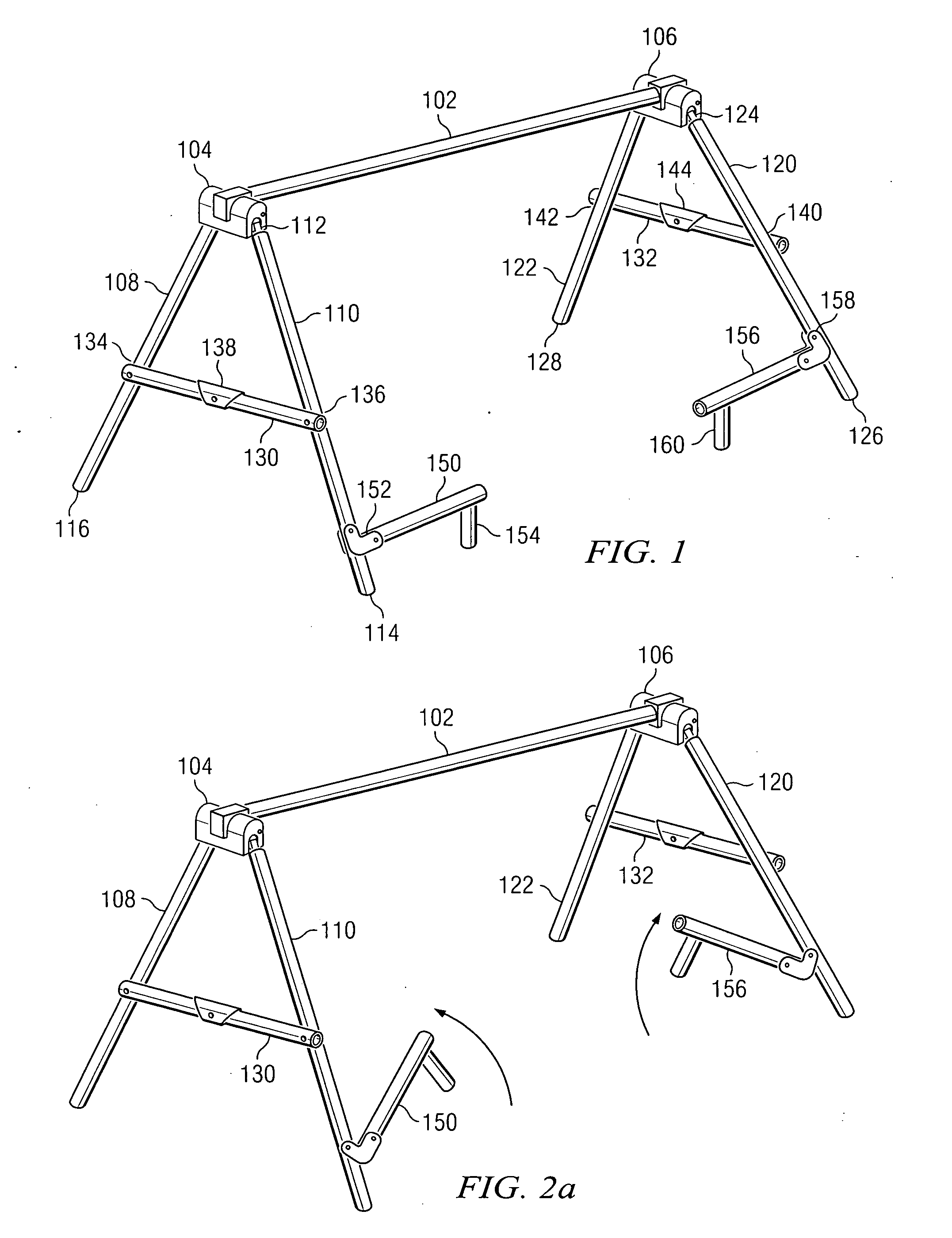
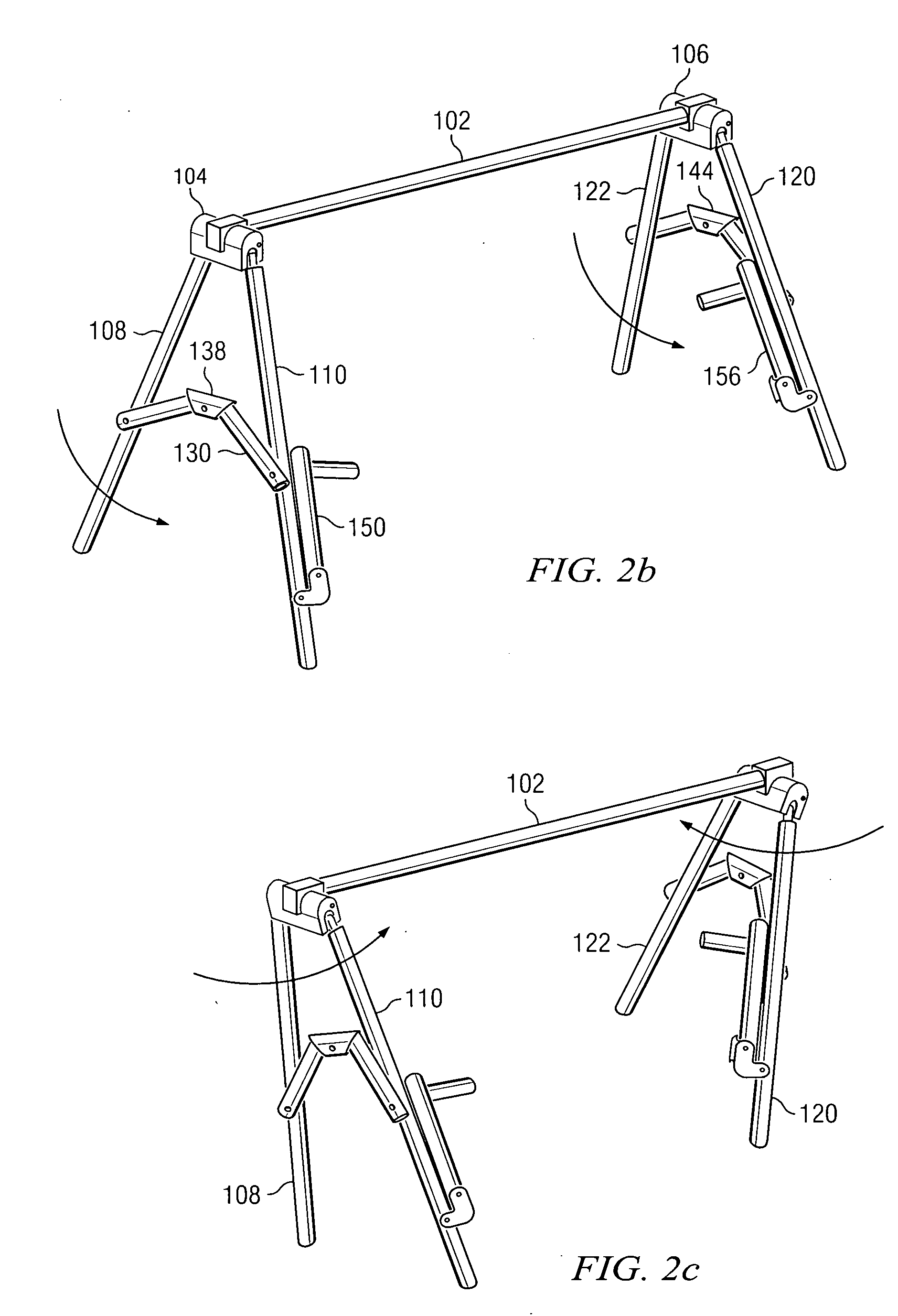
[0014] Referring now to the drawings, and more particularly to FIG. 1, there is illustrated a perspective view of the workout apparatus of the present disclosure. There is provided a main cross member 102 that provides the main support structure, as will be described herein below. The cross member 102 has disposed at one end thereof a first pivoting device 104 and at the other end thereof a second pivoting device 106. Pivoting device 106 has associated therewith two downwardly extending legs 108 and 110 which are tubular in shape in the disclosed embodiment, but could be other shapes and configurations. Leg 110 extends from a pivoting end 112 on the pivoting member 104 downward to a foot 114 and member 108 has a foot 116 and extends downward from a pivoting end (not shown). Similarly, pivoting member 106 has two downwardly extending legs 120 and 122, leg 120 having illustrated a pivoting end 124 pivoted in the pivoting member 106 and a foot end 126 associated with the diametrically ...


PUM


Abstract

A workout apparatus is disclosed. The apparatus includes a crossbar member, a first pivot device disposed on a first end of the crossbar member, and a second pivot device disposed on a second end of the crossbar member. A first set of support legs is provided that comprises a first downwardly extending leg with one end thereof disposed in the first pivot device and pivotable therein and a second downwardly extending leg having a first end pivotably engaged with the first pivot device. The first and second downwardly extending legs are operable to pivot from a substantially parallel relationship to each other to a non-parallel relationship in a diverging form. A restraining device is provided for restraining the first and second downwardly extending legs from diverging beyond a predetermined point. A second set of support legs is provided that comprises a third downwardly extending leg with one end thereof disposed in the second pivot device and pivotable therein and a fourth downwardly extending leg having a second end pivotably engaged with the second pivot device. The third and fourth downwardly extending legs are operable to pivot from a substantially parallel relationship to each other to a non-parallel relationship in a diverging manner. A restraining device is provided for restraining the first and second downwardly extending legs from diverging beyond a predetermined point. The crossbar member and the first and second set of support legs are structurally load bearing to support the weight of an individual suspended from the crossbar member with the distal ends of the first and second downwardly extending legs of the first and second supporting sets disposed on a flat surface. A first protrusion extends from a pivot point proximate to but disposed a short distance from the end of the first leg of the first set of support legs, the first protrusion operable to pivot upward from a first position that is parallel to the crossbar member to a position that is substantially parallel to the first leg of the first set of support legs. A second protrusion is provided that extends from a pivot point proximate to but disposed a short distance from the end of the third leg of the second set of support legs, the second protrusion operable to pivot upward from a first position that is parallel to the crossbar member to a position that is substantially parallel to the third leg of the second set of support legs. The first and second protrusions in the first position extending toward each other from the respective one of the first and third legs in the respective one of the first and second sets of support legs.

Description

CROSS REFERENCE TO RELATED APPLICATIONS [0001] This application claims priority in provisional Application Ser. No. 60 / 512,627, filed Oct. 20, 2003 (Atty. Dkt. LOPZ-26,372).TECHNICAL FIELD OF THE INVENTION [0002] The present invention pertains in general to athletic equipment and, more particularly, to a portable workout device that is collapsible. BACKGROUND OF THE INVENTION [0003] The desire for individuals to maintain some level of physical fitness has seen an increase in the last one or two decades. Some individuals will pursue a workout regimen in an athletic club which has a great deal of expensive equipment, some equipment being multi-functional in nature and some being associated with only a single function, such as a bench press, dumb bells, etc. However, due to the expense of health clubs, a large number of individuals desire to have the workout equipment in their home. To this end, low cost, portable, multi-functional workout devices have been developed. There are some ho...

Claims


Application Information

Patent Timeline
IPC IPC(8): A63B1/00A63B23/00A63B23/12
CPCA63B21/00047A63B23/12A63B2210/50A63B23/1236A63B2208/0242A63B23/1218A63B21/4035
Inventor LOPEZ, LEONARD P.
Owner LOPEZ LEONARD P
Learn More