Side pull-resistant slide for zipper

a pull-resistant slide and zipper technology, applied in the field of zipper slides, can solve problems such as increasing costs

Inactive Publication Date: 2005-06-23
CHEER WAVE
View PDF8 Cites 13 Cited by
  • Summary
  • Abstract
  • Description
  • Claims
  • Application Information

AI Technical Summary

Benefits of technology

[0006] In accordance with a first aspect of the present invention, a slide is provided for a zipper the zipper comprising two tapes each including a row of helically arranged teeth sewn to a lateral edge thereof. The slide comprises two opposed boards each having a first end and a second end. The first ends of the opposed boards are connected by a central guide. The second end of at least one of the opposed boards includes two flanges respectively extending along two lateral edges of the at least one of the opposed boards toward the other board, defining a substantially Y-shaped channel between the boards and the central guide to allow passage of the lateral edge of each tape and the teeth of each tape.
[0008] When the tapes are pull sideways away from each other at upper ends of the tapes, one of the teeth of each tape in an associated opening of the Y-shaped channel presses against the inner end edge and its stop corner of the associated flange extension, preventing downward movements of the upper ends of the tapes, thereby preventing opening of the zipper. Resilient retainer and pull member required in the conventional zipper for providing a retaining function are not needed.
[0012] In accordance with a second aspect of the present invention, a slide is provided for a zipper comprising two tapes each including a row of helically arranged teeth sewn to a lateral edge thereof. The slide comprises a board including a first end and a second end, a central guide formed on the first end of the board, and two upright flanges respectively extending along two lateral edges of the board, with a horizontal flange extending inward from an upper end of the upright flange toward the other upright flange, defining a substantially Y-shaped channel between the central guide and the upright flanges to allow passage of the lateral edge of each tape and the teeth of each tape.

Problems solved by technology

However, the pull member, the resilient retainer, and associated arrangements result an increase in the cost.

Method used


Image

  • Side pull-resistant slide for zipper
  • Side pull-resistant slide for zipper
  • Side pull-resistant slide for zipper

Examples


Embodiment Construction

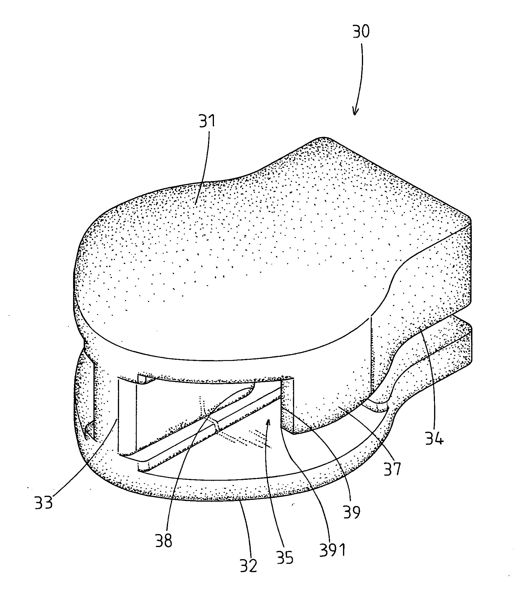
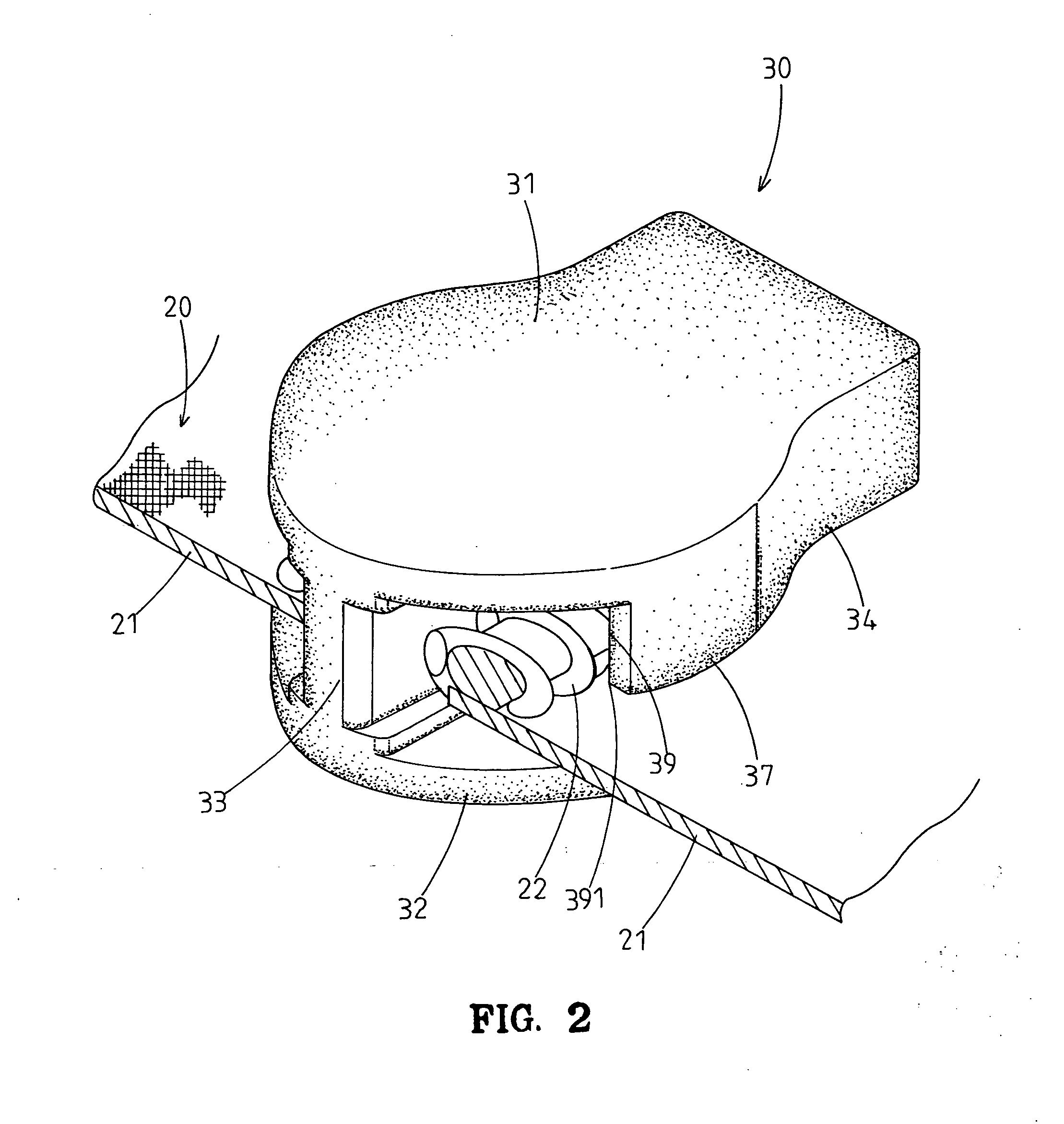
[0033] Referring to FIGS. 2 through 4, a zipper with a side pull-resistant slide in accordance with the present invention is designated by 20 and comprises two tapes 21 and a slide 30. Each tape 21 includes a row of helically arranged teeth 22 sewn to a lateral edge thereof. The slide 30 includes two opposed boards 31 and 32 each having a first end and a second end. The slide 30 further includes a central guide 33 for connecting the first ends of the opposed boards 31 and 32. The second end of at least one of the opposed boards 31 and 32 include two flanges 34 respectively extending along two lateral edges thereof toward the other board 32, 31. In the illustrated embodiment, the second end of the upper board 31 includes two flanges 34 respectively extending along the lateral edges of the upper board 31 toward the lower board 32, defining a substantially Y-shaped channel between the boards 31 and 32 and the central guide 33 to allow passage of the lateral edge and the teeth 22 of eac...


PUM


Abstract

A zipper includes a slide and two tapes each having a row of helically arranged teeth sewn to a lateral edge thereof. The slide includes two opposed boards whose first ends are connected by a central guide. A second end of at least one of the boards includes two flanges respectively extending along two lateral edges thereof toward the other board, defining a substantially Y-shaped channel between the boards and the central guide. A flange extension extends from each flange toward the first end of the board, with a distance between each flange extension and the central guide being the same as a width of each tooth of the zipper. At least one of the flange extensions extends to a level aligned with or beyond a maximum width of an inner end of the central guide and includes an end edge with a stop corner.

Description

BACKGROUND OF THE INVENTION [0001] 1. Field of the Invention [0002] The present invention relates to slide for a zipper. In particular, the present invention relates to a side pull-resistant slide for a zipper, preventing opening of the zipper when subjected to side pull. [0003] 2. Description of the Related Art [0004]FIG. 1 of the drawings illustrates a conventional zipper 20 comprising two tapes 21 and a slider 10. Each tape 21 has a row of teeth 22 sewn to a lateral edge thereof. The slider 10 includes two opposed boards 11 and a central guide 12 for connecting front ends of the opposed boards 11. A rear end of each board 11 includes a flange 13 extending along an edge thereof, defining a substantially Y-shaped channel that allows passage of the lateral edge and the teeth 22 of each tape 21. The flanges 13 extend forward and outward, leaving two openings that are wider than the width of the teeth 22. When the tapes 21 of the zipper 20 are subjected to outward side pull indicated ...

Claims


Application Information

Patent Timeline
Patent Type & Authority Applications(United States)
IPC IPC(8): A44B19/26
CPCY10T24/2561A44B19/26
Inventor YANG, CHUNG-HO
Owner CHEER WAVE
Why Eureka
Try Eureka