Lamp unit mounting structure

a technology for mounting structures and lamps, applied in vehicle interior lighting, transportation and packaging, light and heating equipment, etc., can solve problems such as abnormal sounds and shaken roof sub-assemblies, and achieve the effect of preventing shaken lamps

Active Publication Date: 2007-10-30
YAZAKI CORP
View PDF6 Cites 13 Cited by
  • Summary
  • Abstract
  • Description
  • Claims
  • Application Information

AI Technical Summary

Benefits of technology

[0029]In the above configuration, when an upward force acts on the lamp unit, the upper projection will not interfere with the retaining wall thanks to the provision of the notch in the restriction member, and therefore the lamp unit can be displaced, thereby allowing this force to escape. On the other hand, when a downward force acts on the lamp unit, the lower projection interferes with the retaining wall to restrict the displacement, thereby preventing the downward movement of the lamp unit, and therefore the lamp unit can be positively mounted in such a manner that the shaking of the lamp unit is prevented.

Problems solved by technology

However, when this clearance t is large, there is a fear that the roof sub-assembly is shaken by vibrations or others during the travel of the car, and produces abnormal sounds.

Method used


Image

  • Lamp unit mounting structure
  • Lamp unit mounting structure
  • Lamp unit mounting structure

Examples


Embodiment Construction

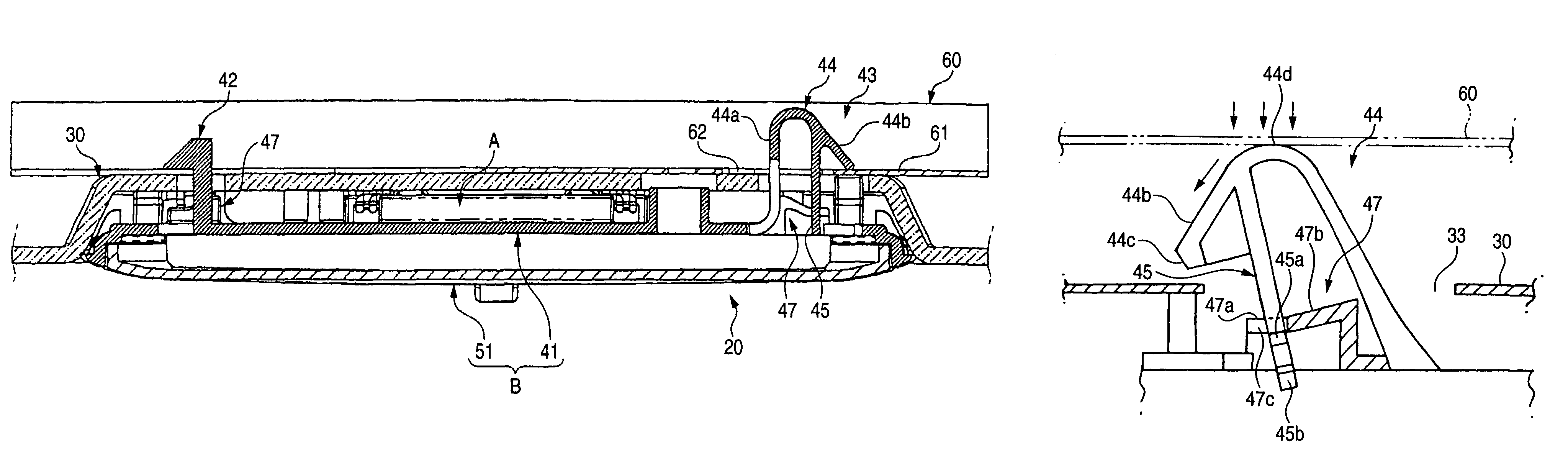
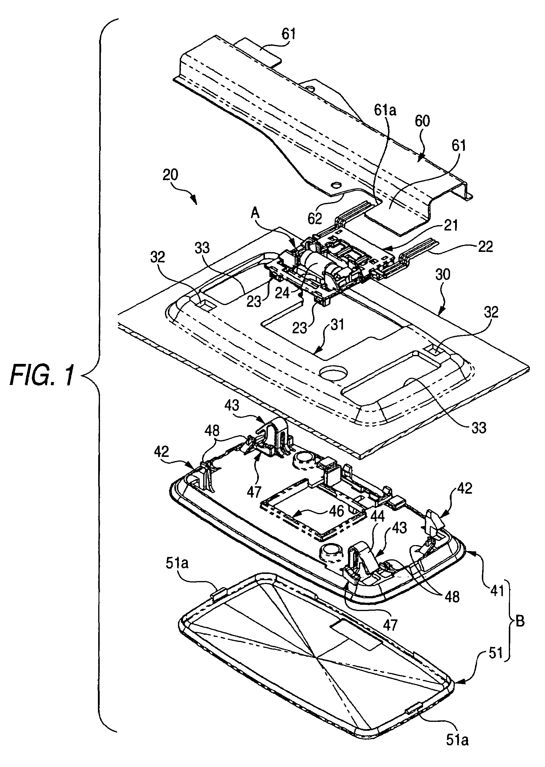
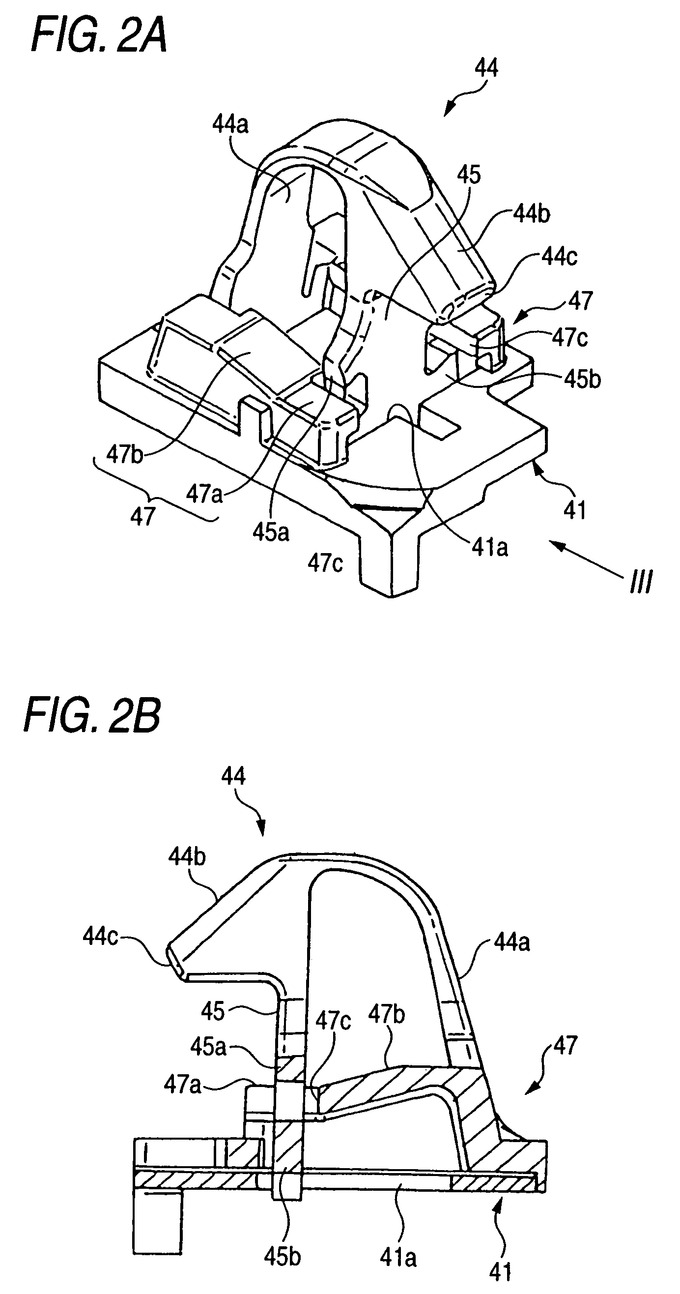
[0046]One preferred embodiment of a lamp unit mounting structure of the present invention will now be described in detail with reference to the accompanying drawings. FIG. 1 is an exploded, perspective view of a room lamp to which one preferred embodiment of the lamp unit mounting structure of the invention is applied, FIG. 2A is an enlarged perspective view of an important portion of a fixing member shown in FIG. 1, FIG. 2B is a cross-sectional view thereof, FIG. 3 is a front-elevational view as seen from a direction III of FIG. 2A, FIG. 4A is an enlarged perspective view of an important portion of a modified example of the fixing member shown in FIG. 2A, FIG. 4B is a cross-sectional view thereof, and FIGS. 5 to 7 are cross-sectional views explanatory of a process of mounting the lamp unit of FIG. 1 on a car body panel.

[0047]The room lamp 20 according to the embodiment, shown in FIG. 1, is a lamp unit which is adapted to be mounted at a lamp-mounting window 31 formed on a roof trim...


PUM


Abstract

A lamp unit mounting structure includes a mounting panel having a mounting portion, a lamp unit, an elastic fixing member and a restricting member. The elastic fixing member is provided on the lamp unit, and includes a first portion which is extended from the lamp unit, a second portion which has a substantially U-shape, and has a first end being integrally connected to the first portion, a third portion which is extended from a second end of the second portion toward the lamp unit. The engagement portion engages the mounting portion of the mounting panel. The restricting member is provided on the lamp unit, and restricts a movement of the elastic fixing member in a mounting and dismounting direction of the engagement portion relative to the mounting panel. The restricting member has an escape portion which allows a movement of the elastic fixing member toward the lamp unit.

Description

BACKGROUND OF THE INVENTION[0001]This invention relates to a lamp unit mounting structure.[0002]There has heretofore been proposed a lamp unit mounting structure of the type in which an interior wall member (covering a car body panel), such as a roof trim or a door trim, and a lamp unit, such as a room lamp or a courtesy lamp, are simultaneously fixed to the car body panel, thereby reducing the time and labor required for an assembling (fixing) operation in a car-assembling line (see JP-A-2001-97112).[0003]FIG. 10 is a longitudinal cross-sectional view explanatory of a related room lamp-mounting structure disclosed in JP-A-2001-97112 or others. In the room lamp-mounting structure shown in FIG. 10, a room lamp 1 and a roof trim 2 are provisionally fixed to each other by a provisionally-fixing member 4, and also the room lamp 1 and a roof reinforcing member 3 of the car body are completely fixed to each other by a completely-fixing member 5. By doing so, the room lamp 1 and the roof t...

Claims


Application Information

Patent Timeline
Patent Type & Authority Patents(United States)
IPC IPC(8): B60Q1/26B60R13/02B60Q3/02F21W106/00
CPCB60Q3/0203B60Q3/51
Inventor OKABE, TOSHIAKIGOTO, YASUNOBUNAGAI, KENTARO
Owner YAZAKI CORP
Why Eureka
Try Eureka