Ultrasonic flowmeter

Active Publication Date: 2005-06-23
ENDRESS HAUSER FLOWTEC AG
View PDF11 Cites 19 Cited by
  • Summary
  • Abstract
  • Description
  • Claims
  • Application Information

AI Technical Summary

Benefits of technology

[0034] The low power supply needed to operate the device allows for the ultrasonic flowmeter to be designed as an intrinsically safe system. Intrins

Problems solved by technology

Where flowmeters are remotely located though, such a requirement is undesirable due to the significant costs of cabling.
Whenever a low level signal of only four milliamps is transmitted, very little power is available to the measurement device.
Accordingly,

Method used


Image

  • Ultrasonic flowmeter
  • Ultrasonic flowmeter
  • Ultrasonic flowmeter

Examples


Example

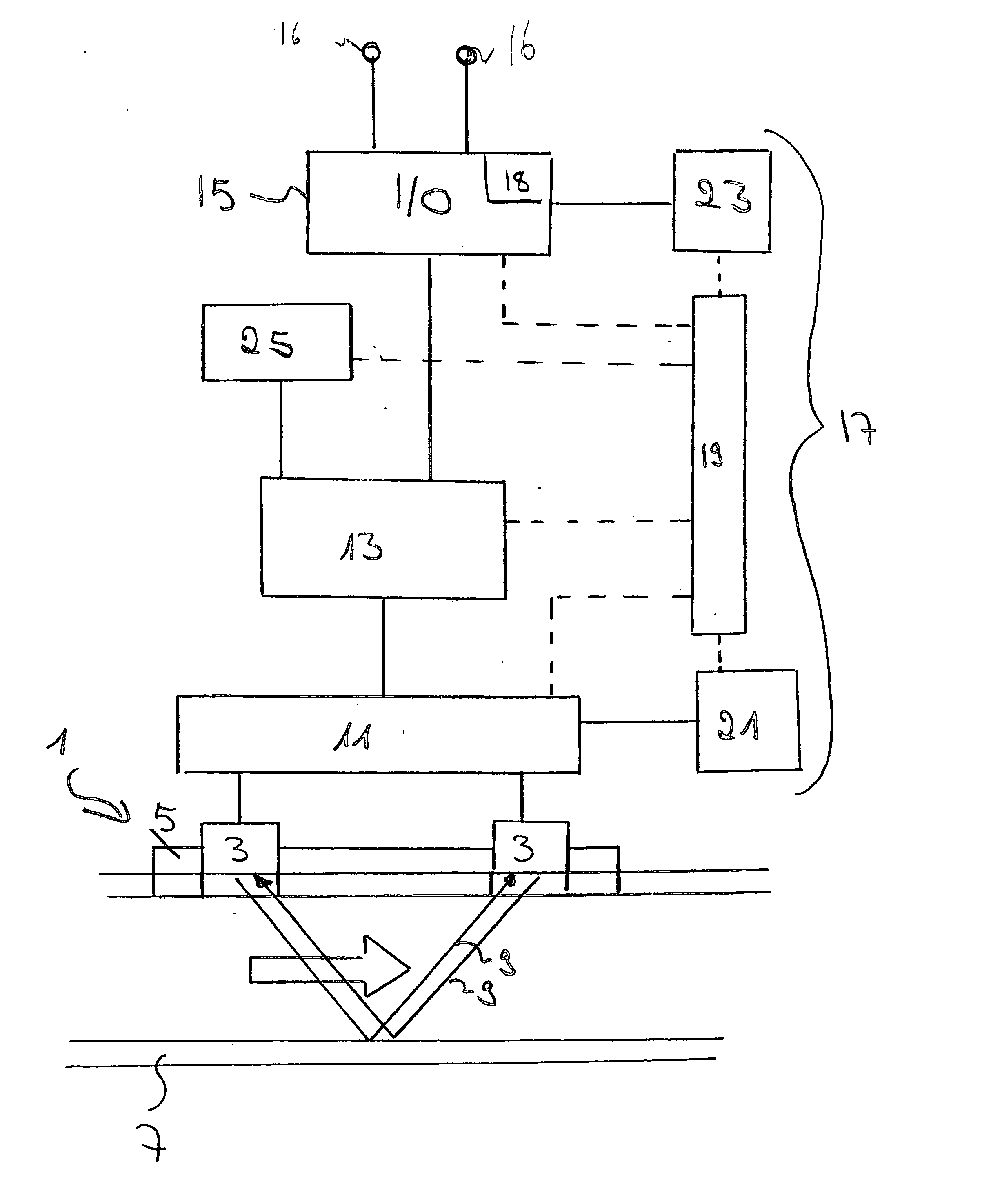
DETAILED DESCRIPTION OF THE DRAWINGS

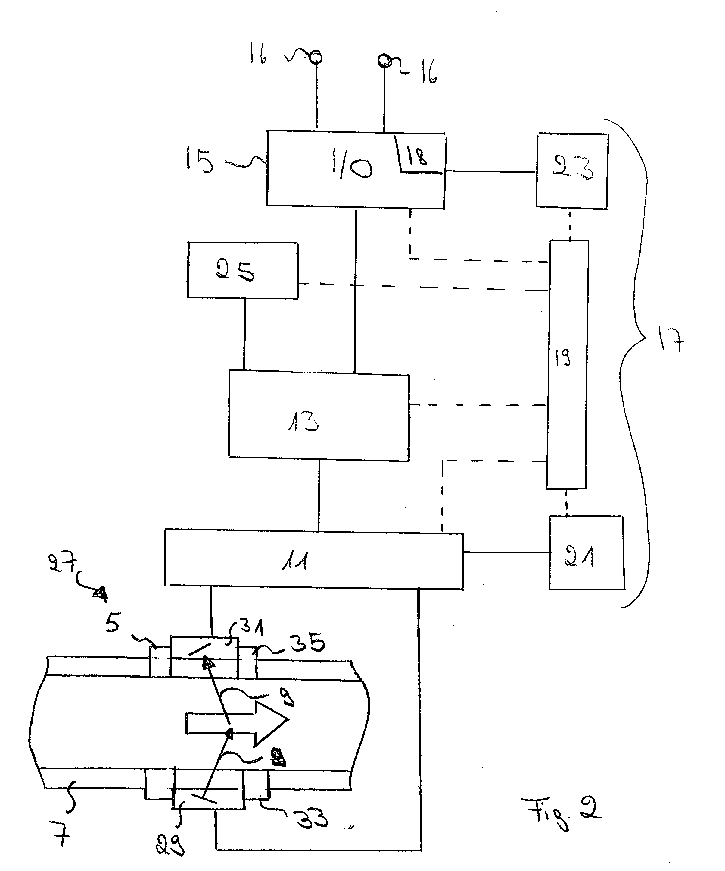
[0038]FIG. 1 shows a schematic diagram of a low power ultrasonic transit time flowmeter to be powered by a two-wire power supply loop. It comprises an ultrasonic flow sensor 1. The ultrasonic flow sensor 1 comprises two ultrasonic transducers 3. The transducers 3 are electro-mechanical transformers, for example piezoelectric elements. Emission of ultrasonic signals 9, i.e. ultrasonic pulses or beams, is initiated by a drive circuit and ultrasonic signals 9 received by the transducers 3 are amplified by an amplifier circuit for further processing. The transducers 3 are mounted on a rack 5 on a pipe 7. One ultrasonic transducer 3 is located upstream of the other. A flow rate of a fluid inside the pipe 7 is to be measured.

[0039] Both ultrasonic transducers 3 serve as transmitters and as receivers for ultrasonic signals 9. In operation, each ultrasonic transducer 3 transmits an ultrasonic signal 9 into the pipe 7. The signal 9 is reflected by the op...


PUM


Abstract

A low power ultrasonic flowmeter to be powered by a two wire power supply loop is described, comprising: an ultrasonic flow sensor (1, 27), a signal processing unit (13) for determining a measurement result based on measurements performed by the ultrasonic flow sensor (1, 27), an input/output unit (15) to be connected to the two wire loop, for controlling a current of the power supplied to represent the measurement result, for receiving power from the power supply loop, and a power management system (17), for an energy efficient distribution of the power supplied to the flowmeter via the input/output unit (15), comprising storage means (21, 23) for storing energy during times of low power consumption and resupplying the stored energy during times of high power consumption.

Description

BACKGROUND AND SUMMARY OF THE INVENTION [0001] The present invention relates to an ultrasonic flowmeter. [0002] Ultrasonic flowmeters are commonly used devices for measuring a flow of a liquid through a pipe. In various branches of industry, for example in the chemical industry or in the pharmaceutical industry, the measurement data obtained by flowmeters is used to control complex industrial processes. [0003] Ultrasonic flowmeters use acoustic waves or vibrations of a frequency of more than 20 kHz. Depending on the design, they use either wetted or non-wetted transducers on the pipe perimeter to couple ultrasonic energy with the fluid in the pipe. [0004] Some ultrasonic flowmeters operate on the Doppler effect, whereby the transmitted frequency is altered linearly by being reflected from particles and bubbles in the fluid. The frequency shift is linearly proportional to the rate of flow of materials in the pipe and is used to develop a signal proportional to the flow rate. [0005] I...

Claims


Application Information

Patent Timeline
IPC IPC(8): G01F1/66G01F15/06G01R21/00
CPCG01F15/06G01F1/667
Inventor SCHAFFER, JOESYLVIA, DEAN
Owner ENDRESS HAUSER FLOWTEC AG
Why Eureka
Try Eureka