
Autonomic control of power subsystems in a redundant power system

a power subsystem and power management technology, applied in the direction of dc source parallel operation, liquid/fluent solid measurement, instruments, etc., can solve the problems of system complexity further increasing, communication channels equally susceptible to failure, and serious safety hazards

Inactive Publication Date: 2004-05-11
IBM CORP
View PDF23 Cites 108 Cited by
  • Summary
  • Abstract
  • Description
  • Claims
  • Application Information

AI Technical Summary

Problems solved by technology

Many high reliability systems require redundant power to permit the system to continue normal operations in the event of a power subsystem failure.
Certain problems are associated with power subsystems that involve more redundancy than N+1.
For example, the power must be dynamically managed to ensure that too much power is not placed on the power bus (which can create a serious safety hazard).
System complexity further increases when the power subsystems are located apart from each other.
However, communication channels are equally susceptible to failure, and / or loss of connectivity between the power nodes.

Method used


Image

  • Autonomic control of power subsystems in a redundant power system
  • Autonomic control of power subsystems in a redundant power system
  • Autonomic control of power subsystems in a redundant power system

Examples


Embodiment Construction

Power Management With Multiple Redundant Power Supplies

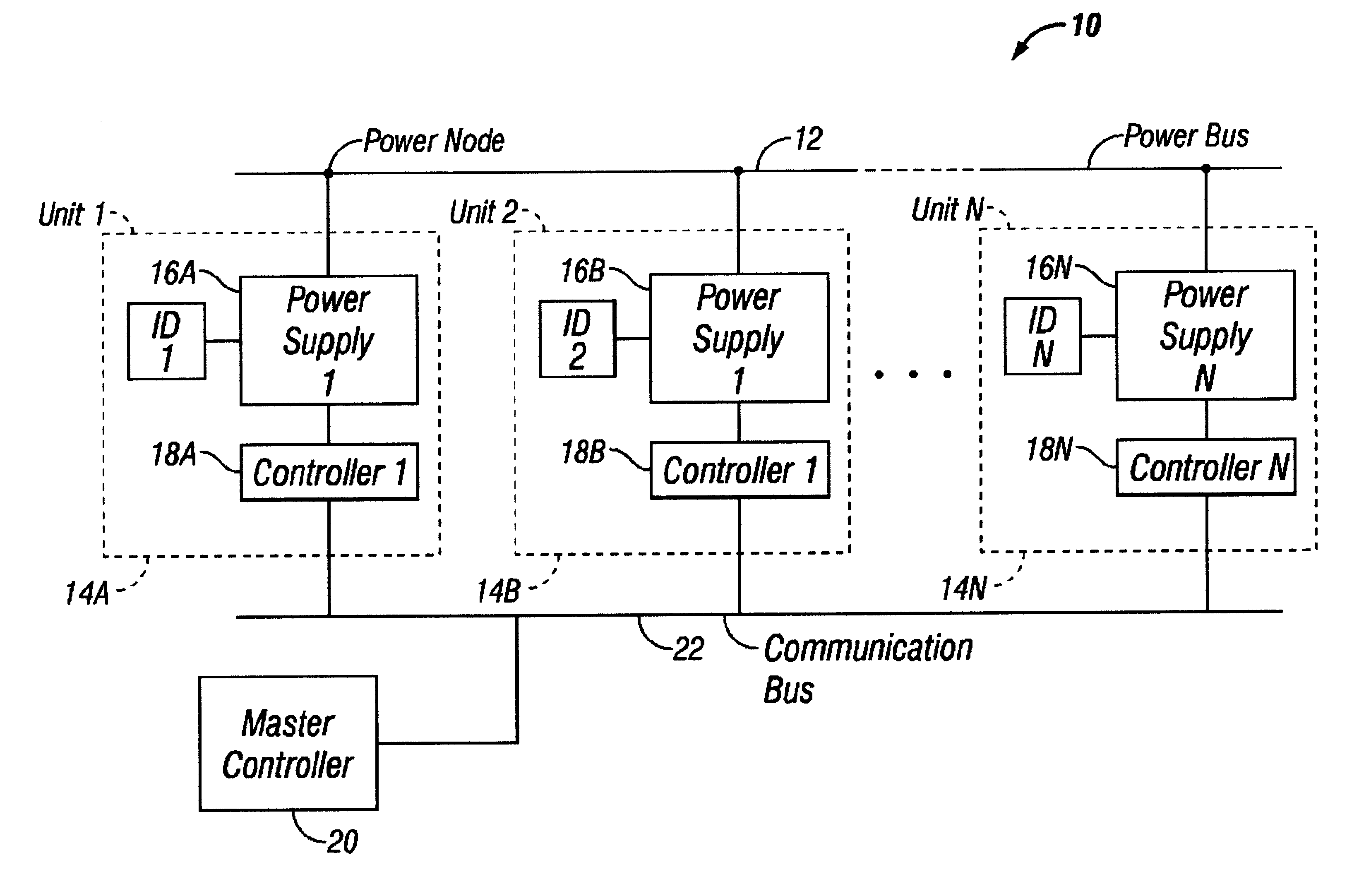
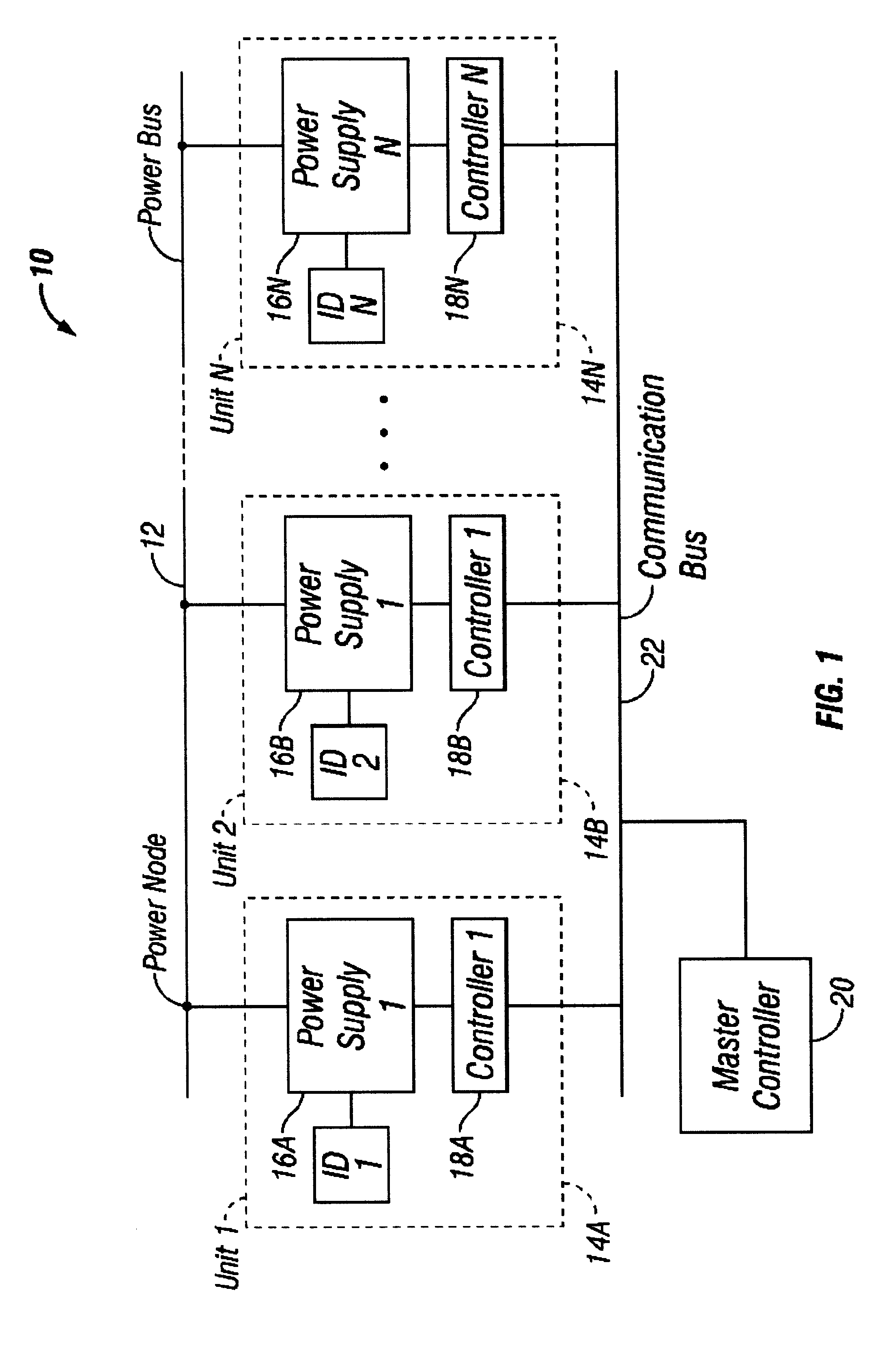
FIG. 1 is a block diagram representation 10 of power management in a redundant power system according to the present invention. As a general overview, the system comprises a plurality of units or power subsystems, 14A, unit 14B . . . unit 14N, each being coupled to a power bus 12 at a power node. Each unit of the present invention includes a power supply 16A, 16B . . . 16N that is capable of supplying power along the power bus 12. As will be described in greater detail below, each unit also comprises a controller 18A, 18B . . . 18N, respectively, which monitors the state of the respective power supply and the power condition on the power bus 12. In the preferred exemplary embodiment, each unit is coupled to a communications bus 22 to permit communication between each unit, including the status state of each power supply. Also in the preferred exemplary embodiment, a master controller 20 is provided to supply commands and data al...


PUM


Abstract

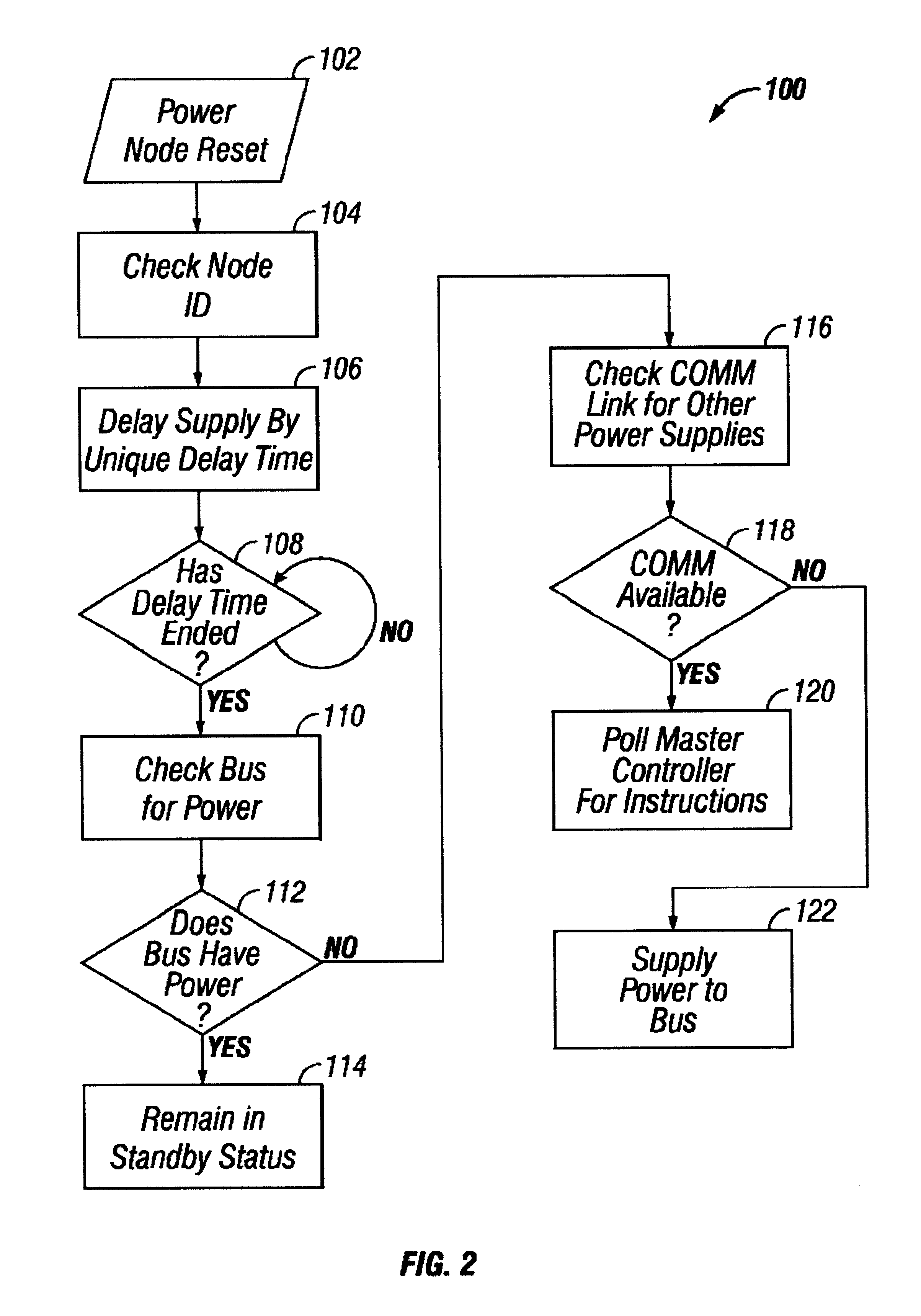
A power management system and method for multiple redundant power supplies. The present invention provides management and control of N+M power supplies, where N represents the minimum number of power supplies required and where M is the number of redundant power supplies (M>1), where any one of the power supplies may be capable of supplying power to all the loads of the power subsystems. In the preferred embodiment each power subsystem includes a power supply and a controller coupled to a power bus. A communication bus is provided common to each power subsystem. During reset or power-on periods, the controllers are programmed to uniquely delay the start time of each power supply, thereby protecting against an overcurrent / overvoltage condition on the power bus during reset periods. A master controller is provided to monitor normal operating conditions of the power subsystems and communication bus. The master controller is programmed to ensure that a predetermined number of power supplies are coupled to the power bus, even in the event of total or partial communication failure.

Description

1. Field of the InventionThe present invention relates to power management in a redundant power system. More particularly, the present invention relates to a power management scheme in a redundant power system where more than one redundant power supplies are available to a power bus. Particular utility for the present invention is power management for the IBM Tape Library System such as described in U.S. Pat. No. 6,356,803; the present invention has general applicability to any high-reliability system that utilizes multiple redundant power subsystems.2. Description of Related ArtMany high reliability systems require redundant power to permit the system to continue normal operations in the event of a power subsystem failure. A common approach involves a technique called N+1, where N is the number of required power subsystems (based on the power demands of the system) and the +1 indicates that there is a single back up power subsystem. While this methodology is convenient for some des...

Claims


Application Information

Patent Timeline
Patent Type & Authority Patents(United States)
IPC IPC(8): H02J3/38H02J1/10
CPCH02J1/10H02J3/38
Inventor BUTKA, DAVIDGOODMAN, BRIAN GERARDJESIONOWSKI, LEONARD GEORGEMCINTOSH, MICHAEL PHILIPROBERTS, ROBIN DANIELYARDY, RAYMOND
Owner IBM CORP
Learn More