Assembling a siphonable filler tube with a check valve on a fuel tank

a technology of check valve and filler tube, which is applied in the direction of bends, process and machine control, instruments, etc., can solve the problems of increasing the number of parts or components to be supplied to the assembly line, the complexity of vehicle assembly, and the problem of further complicated problems

Inactive Publication Date: 2005-06-30
EATON INTELLIGENT POWER LIMITED
View PDF10 Cites 23 Cited by
  • Summary
  • Abstract
  • Description
  • Claims
  • Application Information

AI Technical Summary

Benefits of technology

[0007] The present invention provides a solution to the above-described problem of designing a fuel filler tube or neck assembly including a one-way check valve which may be pre-assembled to the fuel tank and including a nozzle receiving receptacle on the end of the filler tube. The filler tube assembly of the present invention includes a one-way valve for check valve and may be pre-assembled to either a metal fuel tank or a plastic f...

Problems solved by technology

However, this arrangement requires the handling of separate filler tube hose connections and the check valve on the vehicle assembly line and thus increases the number of parts or components to be supplied to the assembly line a...

Method used


Image

  • Assembling a siphonable filler tube with a check valve on a fuel tank
  • Assembling a siphonable filler tube with a check valve on a fuel tank
  • Assembling a siphonable filler tube with a check valve on a fuel tank

Examples


Embodiment Construction

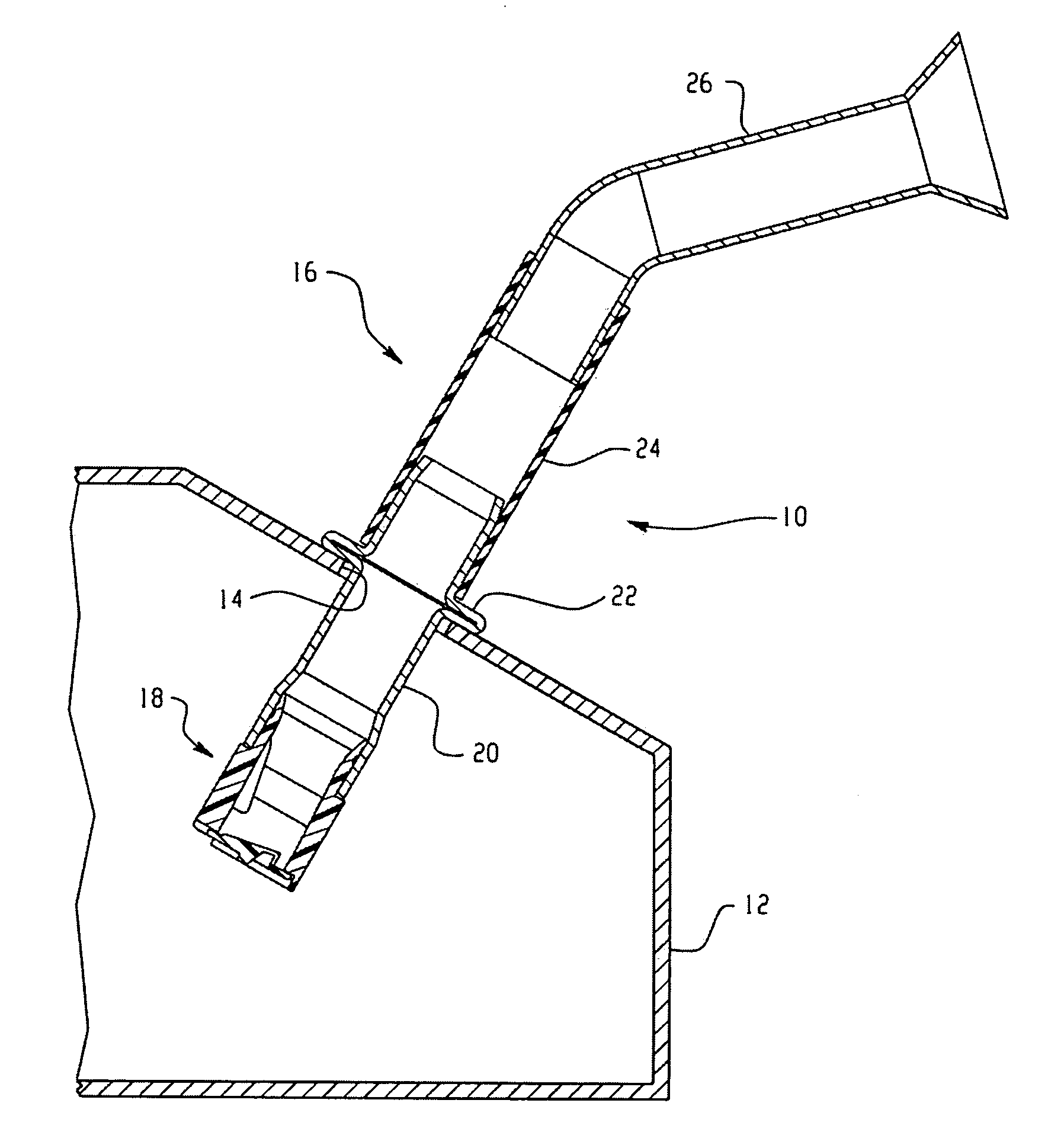
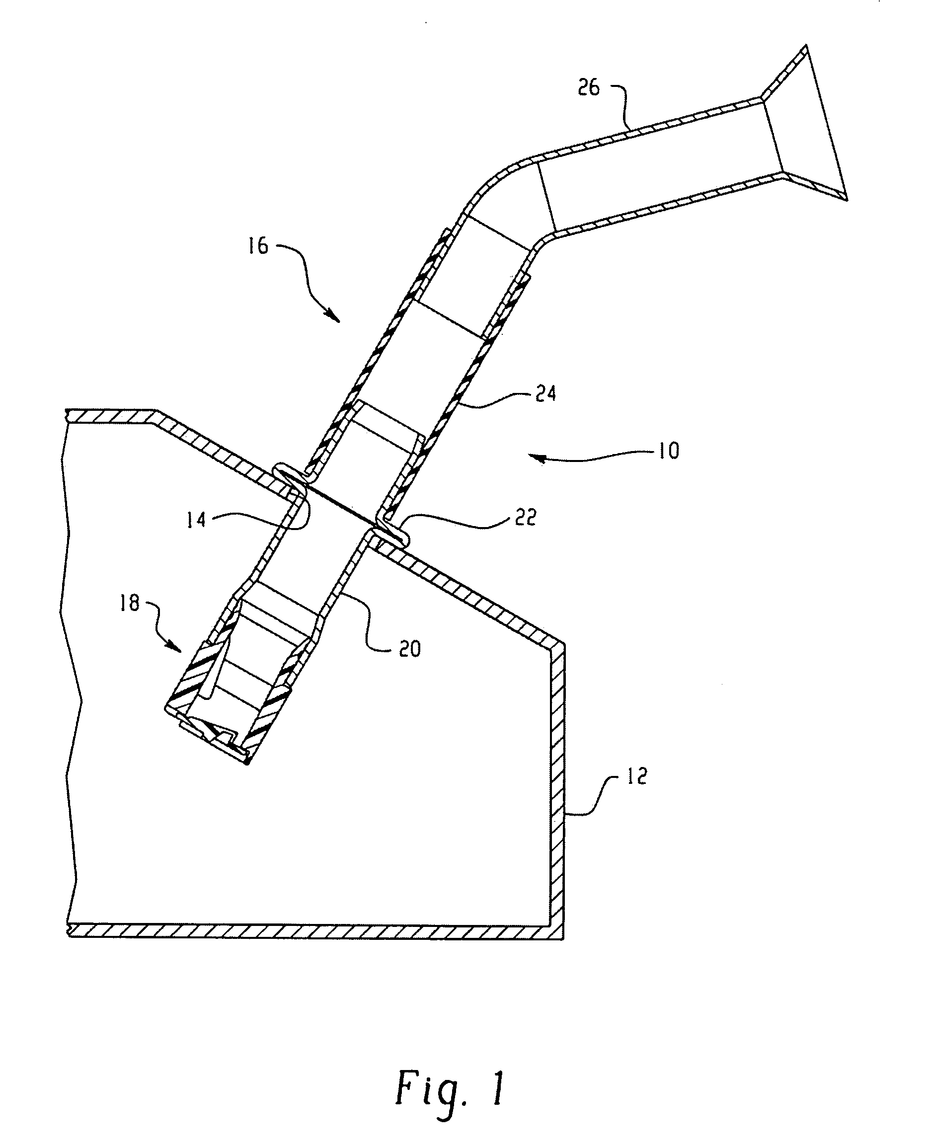
[0016] Referring to FIG. 1, a fuel tank and filler tube assembly employing the present invention is indicated generally at 10 and is shown as applied to a metal a fuel tank 12 having an access opening 14 formed in the upper wall thereof with a filler tube assembly including a one-way valve indicated generally at 16 received therethrough and secured thereon. The assembly 16 includes a one-way valve indicated generally at 18 with a metal attachment tube 20 having one end thereof received over the valve 18; and, tube 20 may include an annular convolution 22 formed thereon and may be secured over the opening 22 and sealed thereon by any suitable expedient as, for example, weldment to the tank 12.

[0017] The upper end of the tube 20 extends outwardly of the tank and has received thereover a filler hose, preferably of elastomeric material as denoted by reference numeral 24 with the lower end thereof received over the upper end of tube 20. The upper end of the hose 24 may have received the...


PUM


Abstract

A fuel filler tube assembly including a one-way valve or check valve. The tube assembly is adaptable for pre-assembly on either a metal or plastic fuel tank and employs a common check valve with an adapter tube for plastic tanks. The valve employs a flapper with spaced ribs for deflecting a siphon hose away from the valve seal; and, the ribs are spaced to maintain the flow stream of he fuel during refueling and facilitating opening of the flapper.

Description

CROSS REFERENCE TO RELATED APPLICATION [0001] This application is a continuation-in-part (CIP) of co-pending application U.S. Ser. No. 10 / 024,252, filed Dec. 21, 2001, in the name of P K Haridass Krishnamoorthy, Charles J. Martin, Maxim V. Zorine, Steven A. Verzyl and Robert P. Benjey for “Assembling A Siphonable Filler Tube With A Check Valve On A Fuel Tank”.BACKGROUND OF THE INVENTION [0002] The present invention relates to filling systems for vehicle fuel tanks and particularly tanks of the type which have a remotely accessible filler tube, for example, of the type accessible through a fuel filler door mounted on the side of the vehicle. Fuel tank installations of this sort are commonly employed on passenger cars and light trucks where it is desired to have the fuel tank filler recessed within the vehicle body and covered by a filler door which blends with the side structure of the vehicle for esthetic or styling purposes. [0003] Vehicle fuel tank filler systems require a positiv...

Claims


Application Information

Patent Timeline
IPC IPC(8): B60K15/04
CPCB60K15/04Y10T137/86372Y10T137/7901Y10T137/2911B60K2015/0477
Inventor KRISHNAMOORTHY, PK HARIDASSMARTIN, CHARLES J.ZORINE, MAXIM V.VERZYL, STEVEN H.BENJEY, ROBERT P.
Owner EATON INTELLIGENT POWER LIMITED
Why Eureka
Try Eureka