
Apparatus for Preventing Extrusion and Method of Manufacturing an Anti-Extrusion Ring

Active Publication Date: 2019-01-17
T LON PROD INC
View PDF14 Cites 1 Cited by
  • Summary
  • Abstract
  • Description
  • Claims
  • Application Information

AI Technical Summary

Benefits of technology

The present invention introduces an anti-extrusion ring with a special cut design called JZ-cut. This cut allows for easy installation while still providing support against extrusion and damage to the sealing ring and loader. Furthermore, the JZ-cut prevents nibbling and damage to the sealing ring and loader caused by multiple pressure cycles or extreme temperatures.

Problems solved by technology

Piston systems that are subjected to high temperatures experience thermal expansion, increasing friction between the sealing ring and the interior of the cylinder.
Thermal expansion and high temperatures therefore increase the risk of seal extrusion and seal damage.
Alternately, or in addition to thermal expansion, high fluid pressures increase seal friction and risk of seal extrusion and seal damage.
In either case, friction and pressure each hinder smooth axial movement and may cause the seal to extrude or roll in the gap between the piston and cylinder bore, increasing the opportunity for fluid leakage / seal failure.
Damage to the sealing ring or loader frequently presents itself as “nibbling”, which is simply to say that fragments of the ring / loader are tugged off.
This not only damages the ring / loader, which can no longer offer as effective a seal, but also the system as a whole, introducing chunks of material from the nibbled areas that contaminate the system, which can cause even further damage.
Further, anti-extrusion rings themselves may present a barrier against extrusion, nibbling, and / or rolling of the loader and / or seal ring.
In addition, anti-extrusion rings are generally rigid, making it difficult to s retch over the piston.
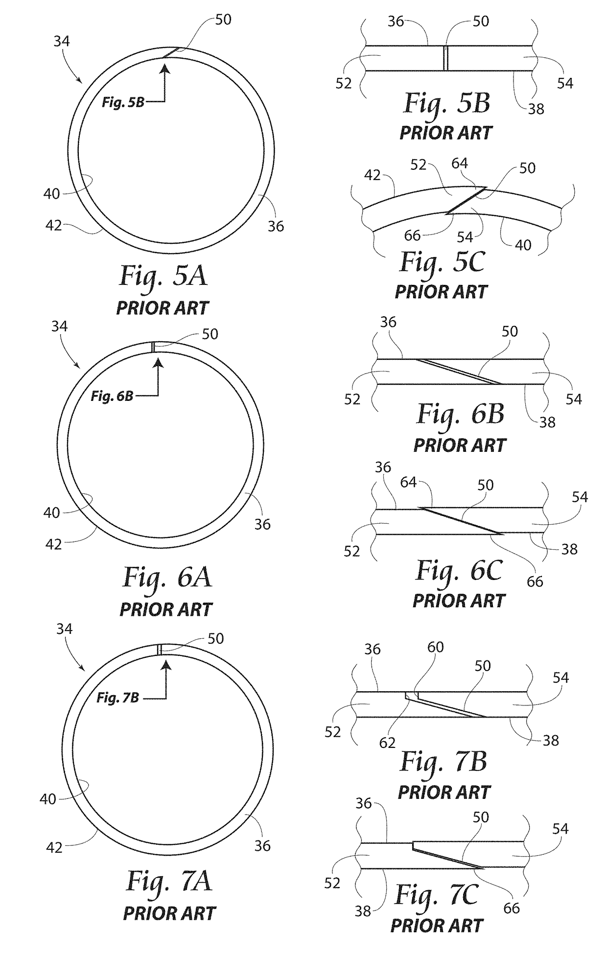
However, once cut, anti-extrusion rings tend to separate or overlap at the split, particularly under the circumstances under which they would be most likely to be used, i.e., high pressure and / or high or low temperature situations.
Such separation or overlap at the split can prevent the anti-extrusion rings from performing effectively in support of the sealing ring and / or loader and may in and of itself cause damage to the system.

Method used


Image

  • Apparatus for Preventing Extrusion and Method of Manufacturing an Anti-Extrusion Ring
  • Apparatus for Preventing Extrusion and Method of Manufacturing an Anti-Extrusion Ring
  • Apparatus for Preventing Extrusion and Method of Manufacturing an Anti-Extrusion Ring

Examples


Embodiment Construction

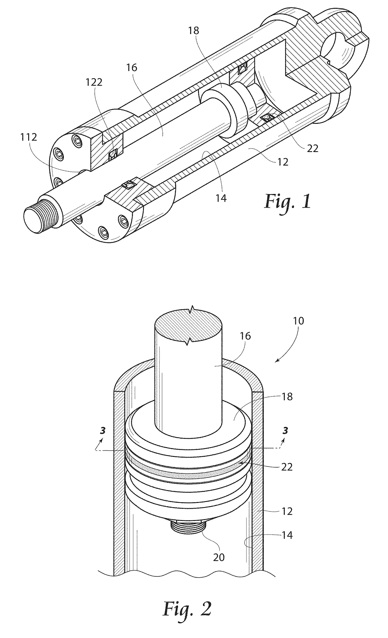
[0039]As seen in FIG. 2, an exemplary piston system 10 comprises a cylinder 12 having an interior surface 14, a rod 16, a piston 18, and a threaded connection element 20. A seal assembly 22 is situated around the circumference of piston 18 in compressing engagement with interior surface 14.

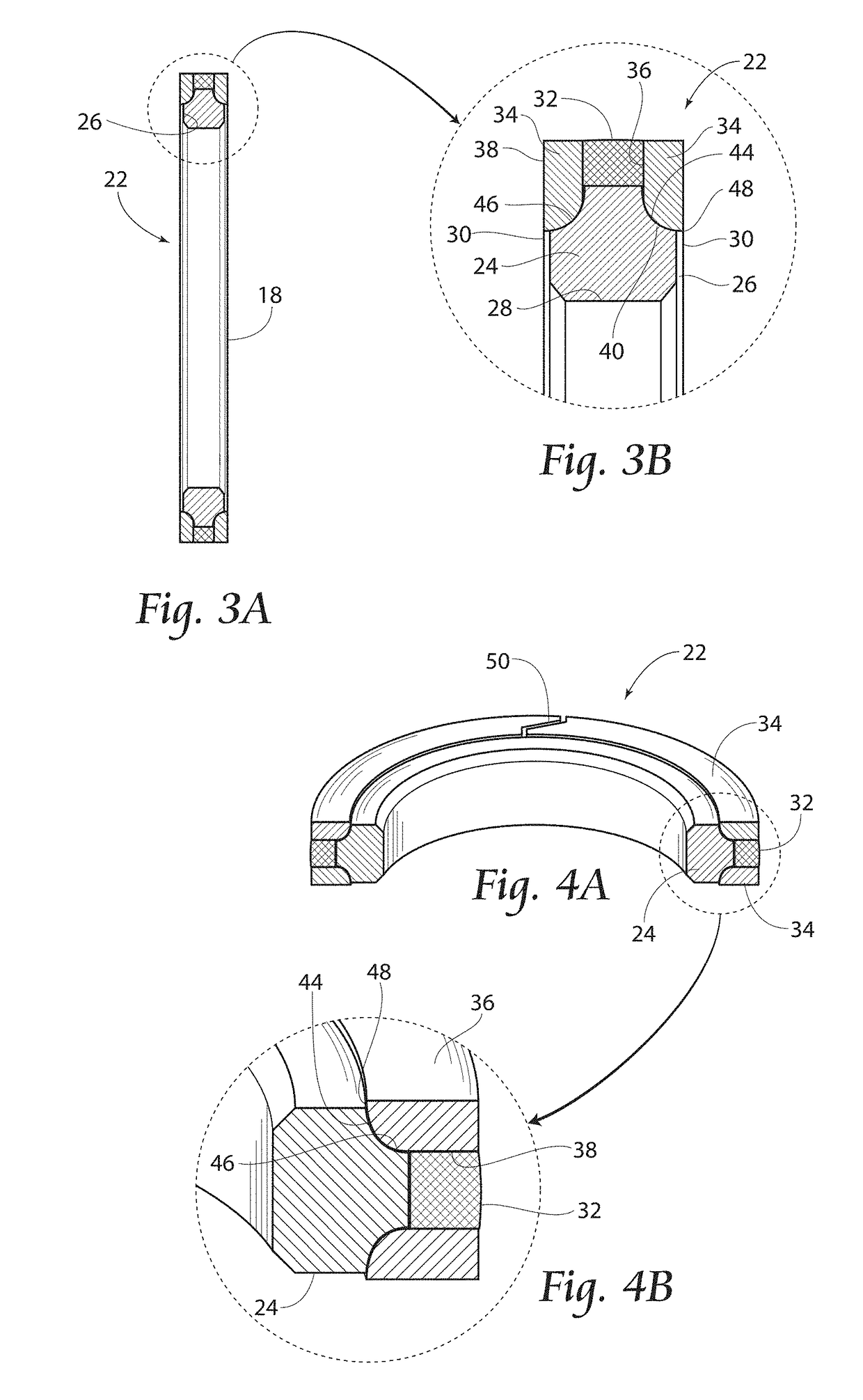
[0040]FIGS. 3A and 3B illustrate an embodiment of the present invention, i.e. seal assembly 22, in place on piston 18. Specifically, seal assembly 22 includes a loading member 24 which is preferably seated within a piston groove 26 having a groove surface 28 and groove walls 30, and a sealing member 32 which loading member 24 urges into sealing contact with interior surface 14 of cylinder 12. In a preferred embodiment, seal assembly 22 further includes a pair of anti-extrusion rings 34, one on either side of sealing member 32. However, as previously indicated, a single anti-extrusion ring 34 could be employed, in which case sealing member 32 could be eliminated.

[0041]Anti-extrusion rings 34 have a...


PUM


Abstract

An anti-extrusion ring for supporting a sealing unit of a piston or rod system is disclosed. The anti-extrusion ring is split across two surfaces for ease of installation and the split is configured to effectively prevent extrusion at either split surface and eliminate nibbling of the sealing components.

Description

BACKGROUND OF THE INVENTION[0001]Most hydraulic or pneumatic systems employ elastomeric and / or plastic sealing rings to prevent the flow of pressurized fluid past the system's piston member. Such sealing rings are typically held into sealing compression against the interior of the system's piston cylinder by a loader support member. The loader is seated in a radial groove around the piston such that it provides a loading force to seal any gaps between the rod surface and the surface of the interior of the cylinder.[0002]Piston systems that are subjected to high temperatures experience thermal expansion, increasing friction between the sealing ring and the interior of the cylinder. Thermal expansion and high temperatures therefore increase the risk of seal extrusion and seal damage.[0003]Alternately, or in addition to thermal expansion, high fluid pressures increase seal friction and risk of seal extrusion and seal damage. In either case, friction and pressure each hinder smooth axia...

Claims


Application Information

Patent Timeline
IPC IPC(8): F16J9/14
CPCF16J9/14F16J15/166
Inventor SCHARRER, JON
Owner T LON PROD INC
Learn More