Contact element

Active Publication Date: 2017-03-02
ROBERT BOSCH GMBH
View PDF5 Cites 0 Cited by
  • Summary
  • Abstract
  • Description
  • Claims
  • Application Information

AI Technical Summary

Benefits of technology

The present invention is based on the recognition that when assembling a contact element in a plug connector, it is important to protect the sealing lamellae of the sealing mat from damage during the insertion of the contact element. To prevent this, the contact body is designed to have a smooth and rounded outer contour, and the crimping process is used to attach the wire strand to the contact body. This creates a sealing geometry that encloses the cable insulation and ensures a reliable sealing effect.

Problems solved by technology

However, the demands imposed by the fastening process, such as a crimping process, often considerably limit the shape of the holding region, e.g., a crimping region, so that its form can be optimized only to a limited extent, so that that damage to the sealing lamellae of the sealing mat is prevented in a reliable manner.
Unfortunately, it is possible that sharp-edged regions of the contact element or, for instance, a pronounced wire strand protrusion (“bushing”), which occurs between the contact body and the wire strand crimping region, result in damage to the sealing lamellae when the contact element is inserted through the sealing mat.
Projecting wire strands and sharp edges are hidden by the cover and thus are no longer able to damage the sealing lamellae of the sealing mat.
This will automatically no longer be possible when the protective element is in the second position.
In addition, the proposed contact element requires no new technologies for fastening the cable, which means that conventional methods may be utilized.
When the contact element is inserted through a narrow opening along the longitudinal axis, the inner walls of the opening may sustain damage.
Because of its larger outer diameter, the contact element is therefore unable to be assembled; in the event that this is possible nevertheless on account of the measurements, it is unable to lock into place in a contact housing of a plug connector in which the contact element is to be installed.
Furthermore, a quality control process that follows the shifting step can be carried out visually in an uncomplicated manner.

Method used


Image

  • Contact element
  • Contact element
  • Contact element

Examples


Embodiment Construction

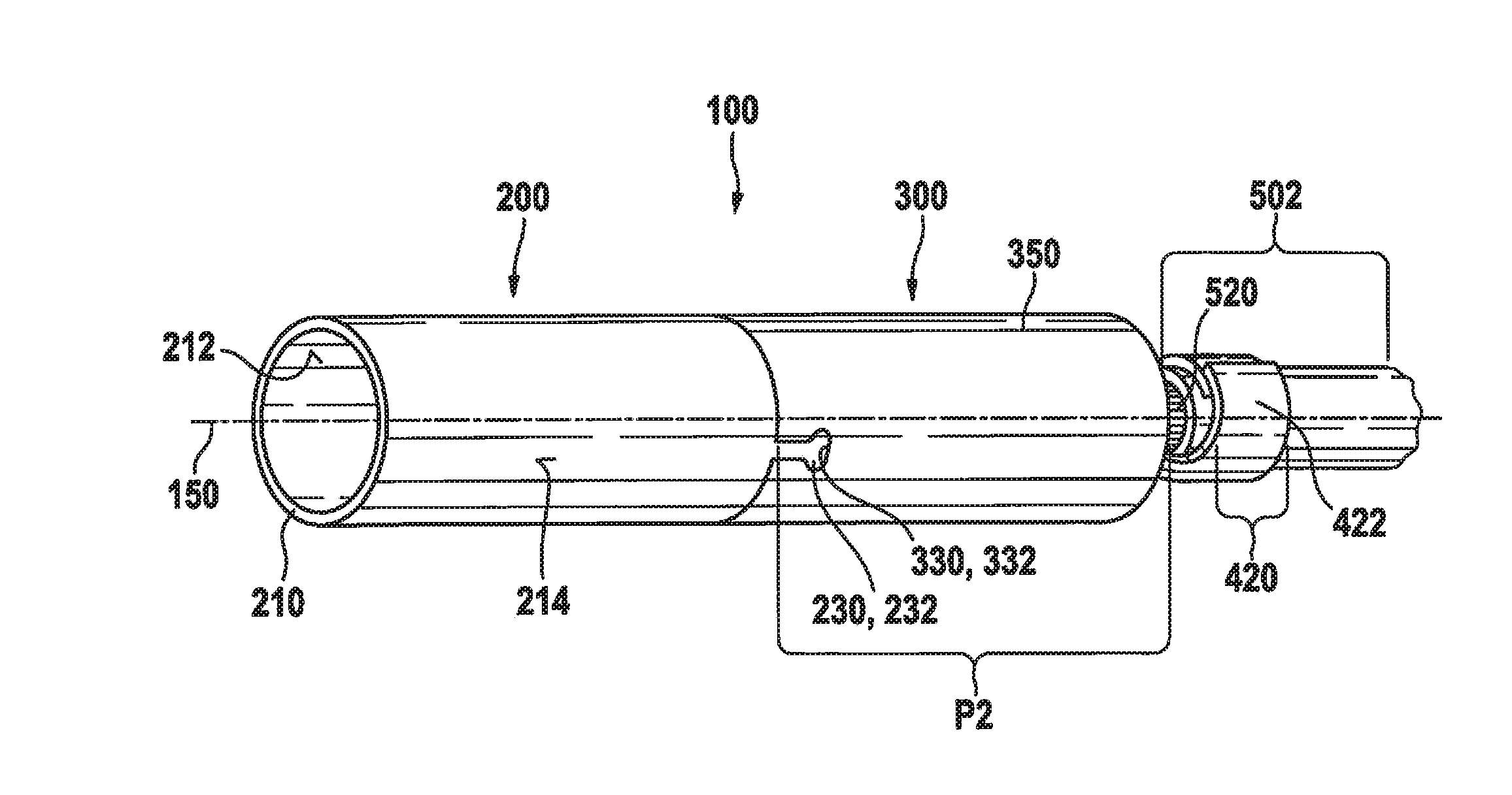
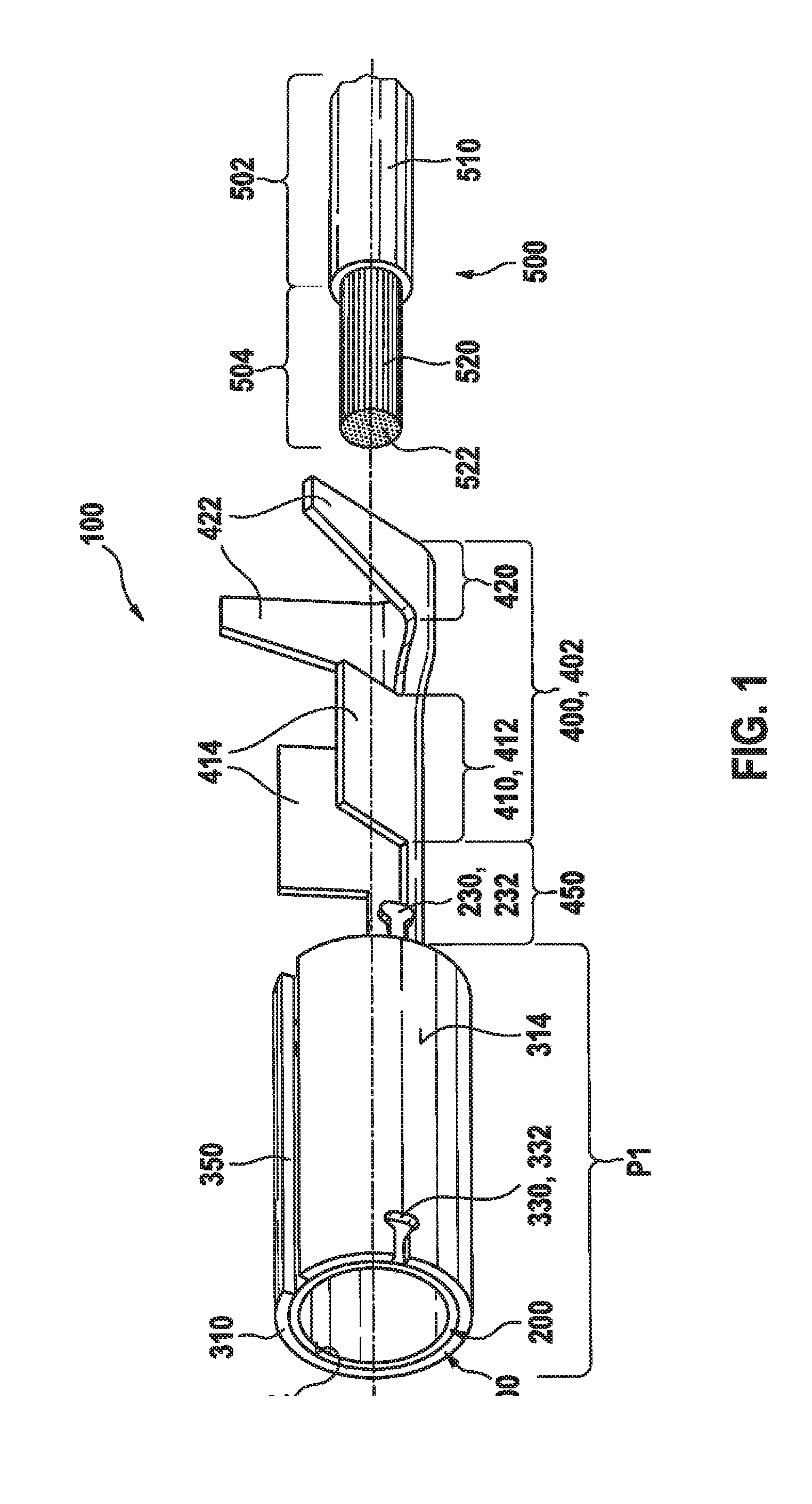
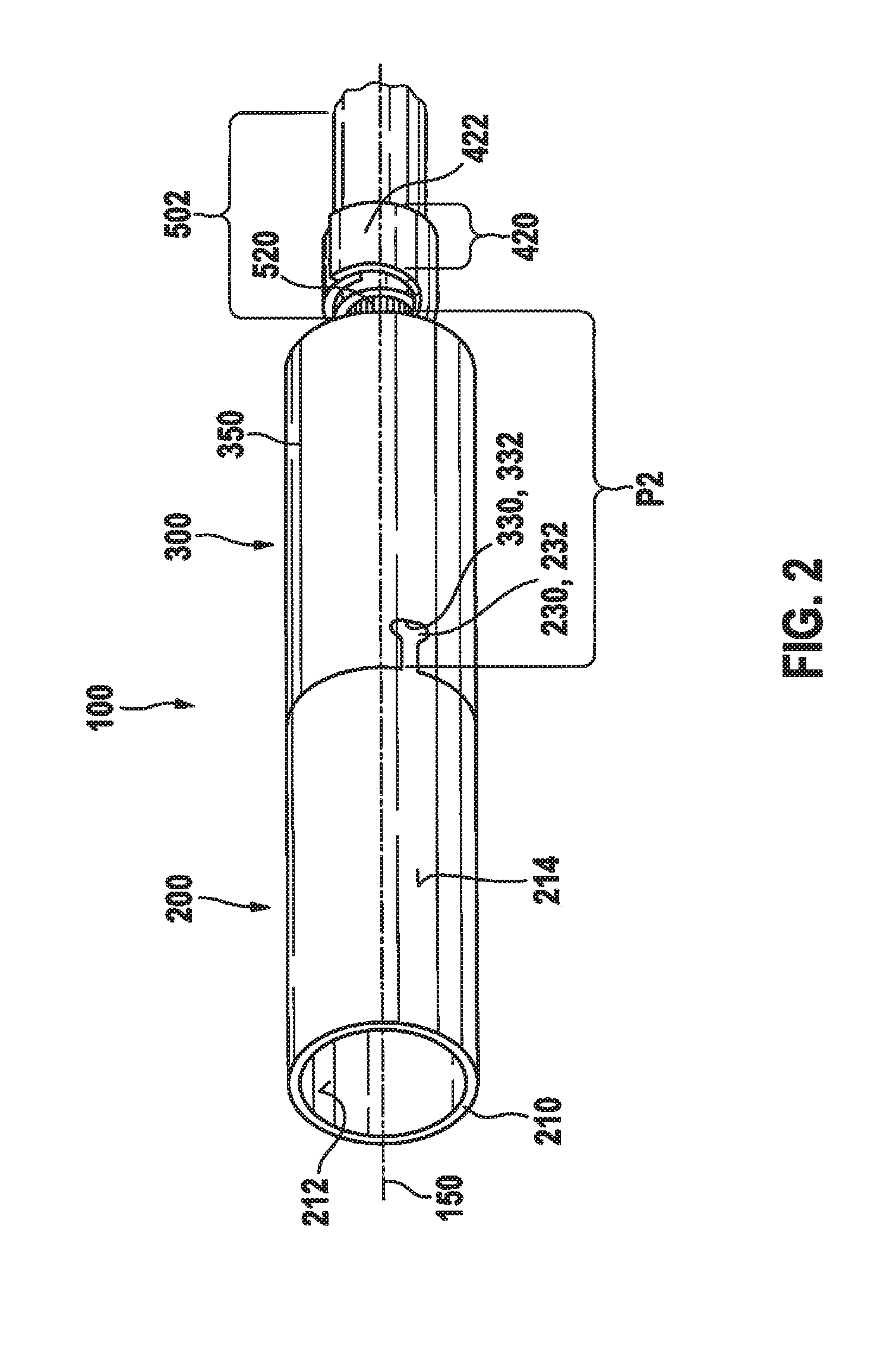
[0047]FIGS. 1 and 2 show a contact element 100, which is produced in a punching-bending process from thin sheet metal, for example. Contact element 100 has a contact body 200, which extends along a longitudinal axis 150. Contact body 200 may have a hollow-cylindrical design such as the form of a hollow circular cylinder, for example, which includes a wall 210 having an inner wall 212 and an outer wall 214. The contact body, for instance, is made from an electrically conductive material, preferably a metal. Contact body 200 may also have an elliptical or rectangular form in a cross-section transversely to longitudinal axis 150, or in general, it may feature a polygonal cross-section.

[0048]In addition, contact element 100 has a cable holder 400, which is connected to contact element 200 and extends along longitudinal axis 150. Cable holder 400 may be connected to the contact body via a collar section 450 or collar region 450.

[0049]Cable holder 400 and collar section 450 are preferably...


PUM


Abstract

A contact element. The contact element has a contact body extending along a longitudinal axis and a cable holder connected to the contact body and extending along the longitudinal axis, wherein the cable holder has at least one retaining section for fixing a cable to the cable holder. The contact element additionally has a protective element. In order to prevent the protruding strands of the cable from damaging the sealing mat when inserting the contact element through the sealing mat, the protective element is displaceable along the longitudinal axis from a first position into a second position, wherein the protective element covers the cable holder in the second position. A method for producing a contact-element / cable arrangement is also described.

Description

BACKGROUND INFORMATION[0001]In multi-pole plug connectors, in which contact elements are plugged into the plug-connector casings or contact housings, sealing mats having sealing lamellae and a separate opening for each contact element are often employed in order to seal the plug connector from entering media along the cables. As a rule, the contact element includes a contact body and a cable holder, which has a holding section. A wire strand crimping region, for example, and possibly also an insulation-crimping region, in which a cable is crimped onto the contact element, are provided in the holding section.[0002]Such a contact element is described in German Patent Application No. DE 10 2011 078 093 A1, for instance.SUMMARY[0003]The present invention is based on the recognition that when the contact element is assembled in the plug connector, the contact body of the contact element is inserted through the sealing mat first; the wire strand crimping region and possibly the insulation...

Claims


Application Information

Patent Timeline
IPC IPC(8): H01R13/44H01R43/04H01R4/18
CPCH01R13/44H01R43/04H01R4/185H01R4/184H01R13/18H01R13/506
Inventor WITTMANN, ROLF
Owner ROBERT BOSCH GMBH
Why Eureka
Try Eureka