
Optimized performance and performance for red-eye filter method and apparatus

a filter and performance optimization technology, applied in the field of flash photography, can solve the problems of objectionable pre-flash, less than desirable position, and unsatisfactory

Inactive Publication Date: 2005-06-30
DIGITALPTICS EURO
View PDF99 Cites 217 Cited by
  • Summary
  • Abstract
  • Description
  • Claims
  • Application Information

AI Technical Summary

Benefits of technology

[0021] The modifying of the area may be performed including the full resolution of the image. The method may include determining the subsample representation utilizing a plurality of sub-filters. The determining of the plurality of sub-filters may be based on one or more of the image size, a suspected red eye region size, filter computation complexity, empirical success rate of said sub-filter, empirical false detection rate of said sub-filter, falsing probability of said sub-filter, relations between said suspected red eye regions, or results of previous analysis of one or more other sub-filters.

Problems solved by technology

This objectionable phenomenon is well understood to be caused in part by a small angle between the flash of the camera and the lens of the camera.
Unfortunately, the pre-flash is an objectionable 0.2 to 0.6 seconds prior to the flash photograph.
Consequently the subject may believe the pre-flash is the actual photograph and be in a less than desirable position at the time of the actual photograph.

Method used


Image

  • Optimized performance and performance for red-eye filter method and apparatus
  • Optimized performance and performance for red-eye filter method and apparatus
  • Optimized performance and performance for red-eye filter method and apparatus

Examples


Embodiment Construction

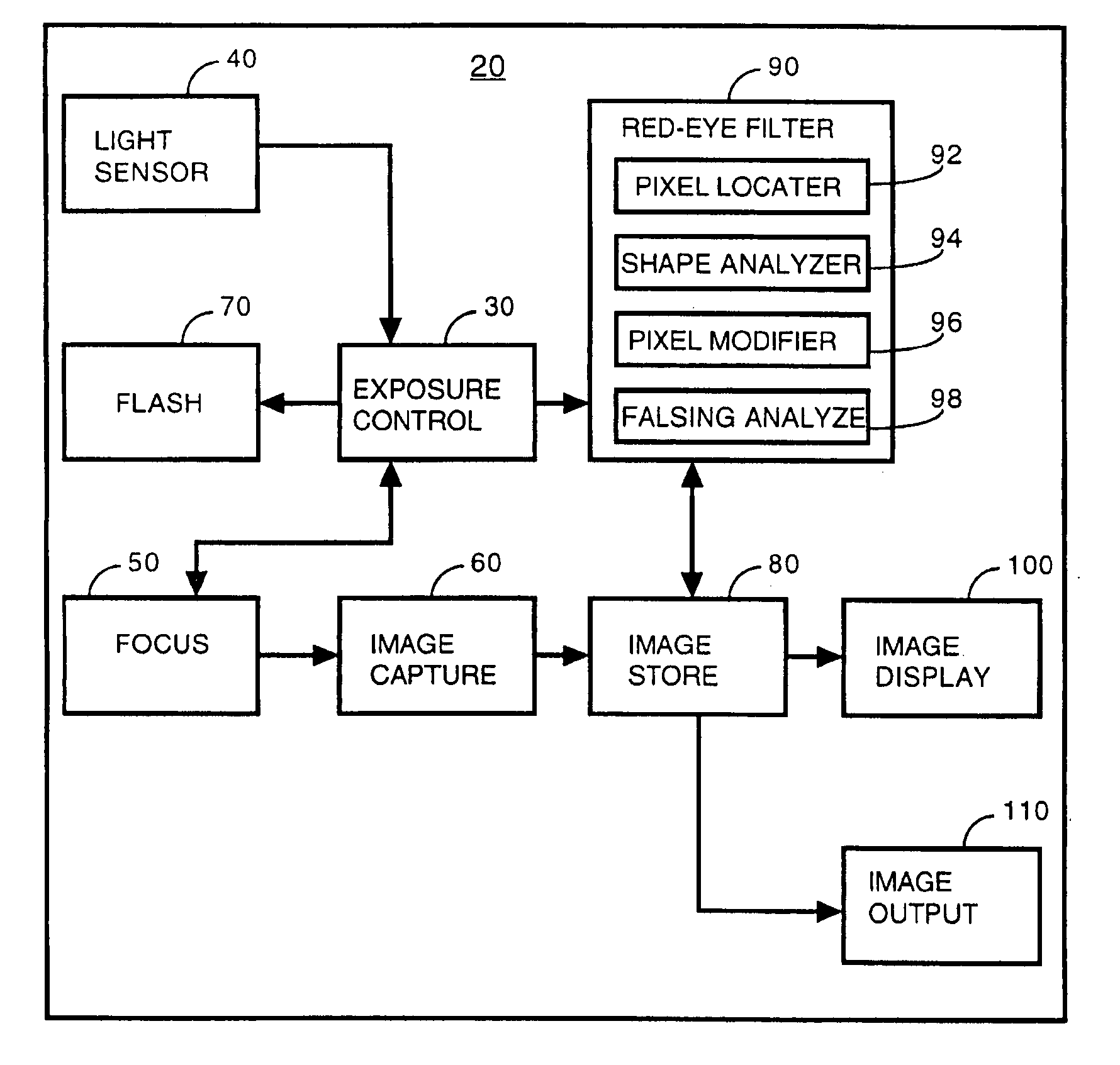
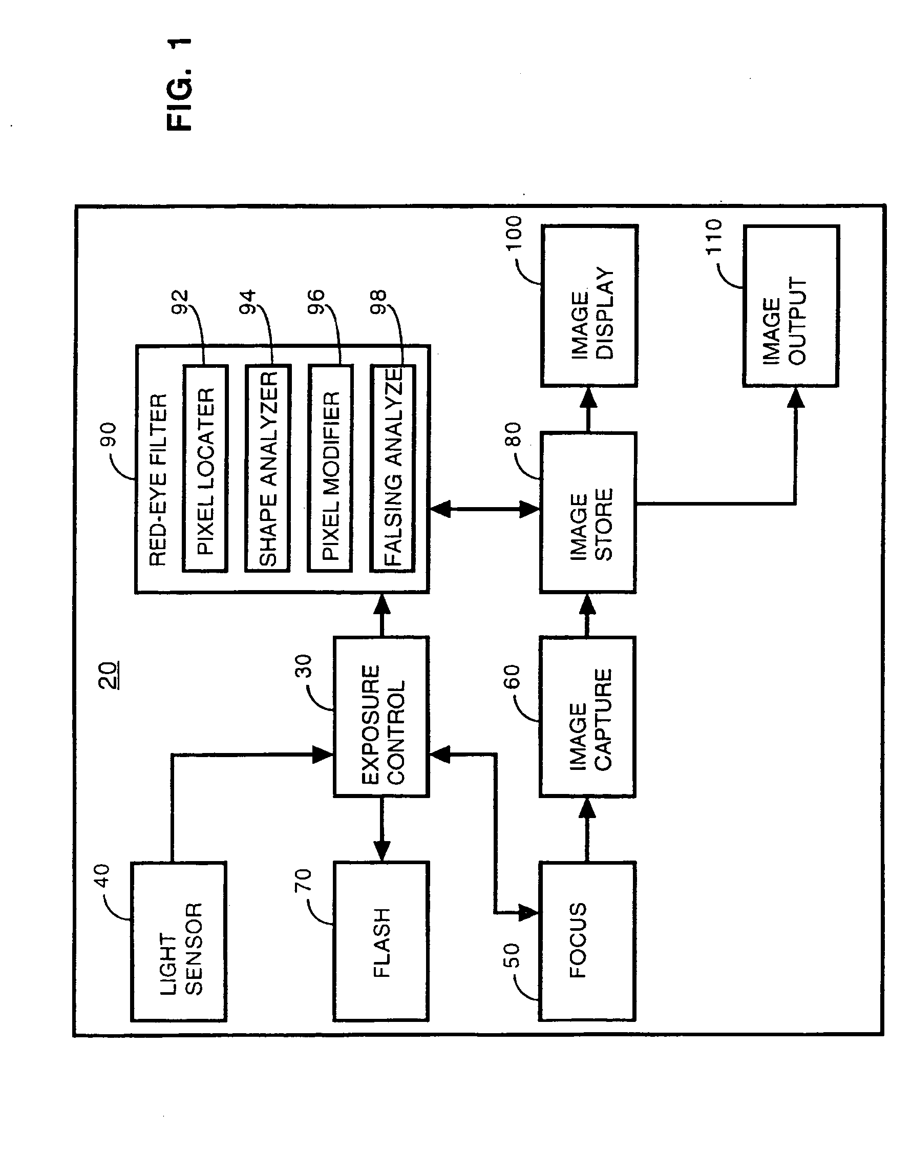
[0033]FIG. 1 shows a block diagram of a camera apparatus operating in accordance with the present invention. The camera 20 includes an exposure control 30 that, in response to a user input, initiates and controls the digital photographic process. Ambient light is determined using light sensor 40 in order to automatically determine if a flash is to be used. The distance to the subject is determined using focusing means 50 which also focuses the image on image capture means 60. The image capture means digitally records the image in color. The image capture means is known to those familiar with the art and may include a CCD (charge coupled device) to facilitate digital recording. If a flash is to be used, exposure control means 30 causes the flash means 70 to generate a photographic flash in substantial coincidence with the recording of the image by image capture means 60. The flash may be selectively generated either in response to the light sensor 40 or a manual input from the user o...


PUM


Abstract

A digital camera has an integral flash and stores and displays a digital image. Under certain conditions, a flash photograph taken with the camera may result in a red-eye phenomenon due to a reflection within an eye of a subject of the photograph. A digital apparatus has a red-eye filter which analyzes the stored image for the red-eye phenomenon and modifies the stored image to eliminate the red-eye phenomenon by changing the red area to black. The modification of the image is enabled when a photograph is taken under conditions indicative of the red-eye phenomenon. The modification is subject to anti-falsing analysis which further examines the area around the red-eye area for indicia of the eye of the subject. The detection and correction can be optimized for performance and quality by operating on subsample versions of the image when appropriate.

Description

PRIORITY [0001] This application is a continuation-in-part application which claims the benefit of priority to U.S. patent application Ser. No. 10 / 635,918, filed Aug. 5, 2003, which is hereby incorporated by reference. This application is related to U.S. patent application Ser. No. 10 / 170,511, filed Jun. 12, 2002, which is a continuation of U.S. patent application Ser. No. 08 / 947,603, filed Oct. 9, 1997, now U.S. Pat. No. 6,407,777, issued Jun. 18, 2002, which is hereby incorporated by reference. This application is also related to U.S. patent application Ser. No. 10 / 635,862, filed Aug. 5, 2003, which is also hereby incorporated by reference.FIELD OF THE INVENTION [0002] The invention relates generally to the area of flash photography, and more specifically to filtering “red-eye” from a digital camera image. BACKGROUND OF THE INVENTION [0003]“Red-eye” is a phenomenon in flash photography where a flash is reflected within a subject's eye and appears in a photograph as a red dot where...

Claims


Application Information

Patent Timeline
Patent Type & Authority Applications(United States)
IPC IPC(8): G06K9/00G06T5/00G06T7/00G06T7/40H04N1/62
CPCG03B15/05G06K9/0061G06K2009/00322G06T7/004G06T7/408G06T2207/10024H04N1/62H04N1/624H04N5/2354G06T5/005G06T2207/30216G03B2215/05G06T7/70G06T7/90G06V40/178G06V40/193H04N23/74G06T5/77
Inventor PRILUTSKY, YURYSTEINBERG, ERANCORCORAN, PETERPOSOSIN, ALEXEIBIGIOI, PETRONELDRIMBAREAN, ALEXANDRUCAPATA, ADRIANNANU, FLORIN
Owner DIGITALPTICS EURO
Learn More