Motorized adjustable workstation

Inactive Publication Date: 2005-07-14
ALLEN NORMAN WALTER
View PDF33 Cites 7 Cited by
  • Summary
  • Abstract
  • Description
  • Claims
  • Application Information

AI Technical Summary

Benefits of technology

[0012] The adjustable workstation system of the present invention increases the user's ability to achieve an ergonomically correct posture with a range of adjustments that are more inclusive of the general po

Problems solved by technology

I have no knowledge of any adjustable workstation utilizing a design that significantly raises the bending moment of a single dri

Method used


Image

  • Motorized adjustable workstation
  • Motorized adjustable workstation
  • Motorized adjustable workstation

Examples


Example

[0026] The present invention relates to a new and improved motorized adjustable workstation. The invention can be utilized in any environment where people would benefit from an adjustable work surface and / or adjustable monitor lift. It is particularly suited for computer workstation solutions.

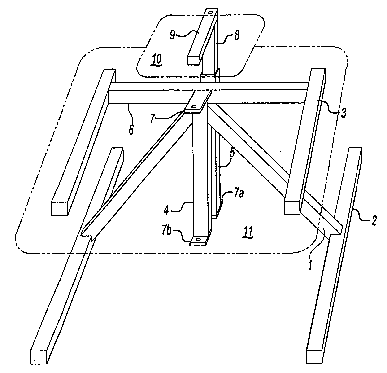
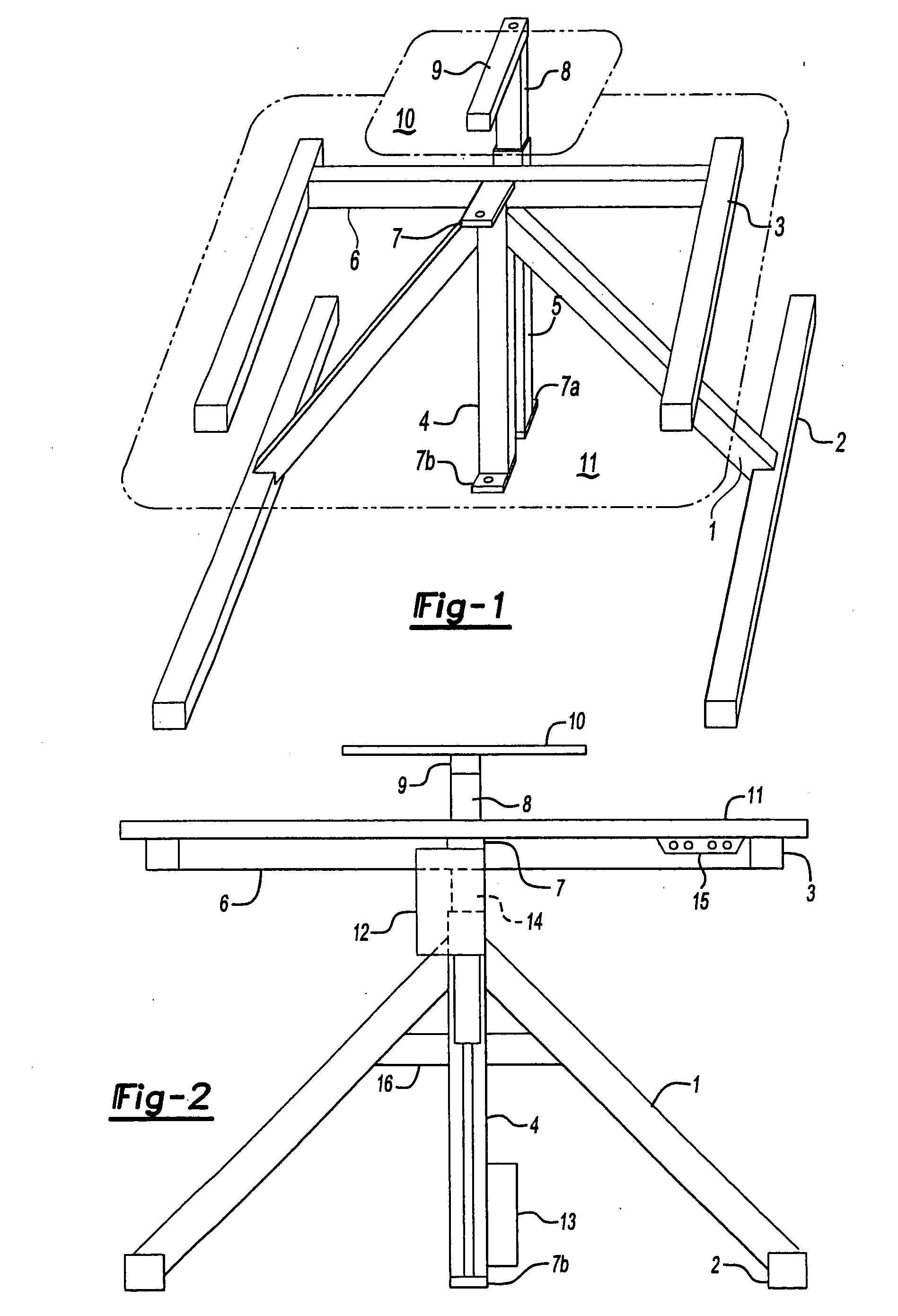
[0027] The preferred embodiment of the workstation as shown in FIGS. 1-3, consists of a base made of tubing that generally includes two feet 2 and two interconnected legs 1 forming a stable bipod that intersects and supports a vertical main drive tube 4 with a means of adjoinment, that approximate 45+ / −degree angles, to form a stable, sturdy structure that raises the bending moment of the main drive tube 4 a significant distance above the floor.

[0028] A main linear actuator 12 (see FIG. 2) raises a main drive shaft 14 slidably disposed within the tube 4 and which supports a bow back 6 with its attached arms 3 and thereby supports a main work surface 11. A monitor lift attachment tube 17 (see ...


PUM


Abstract

The present invention is a new and improved motorized adjustable workstation. The invention base has substantially parallel feet and legs that rise at an angle to support the main drive tube. Attached to the main drive tube is a linear actuator that raises the main work surface. The preferred embodiment of the invention incorporates an adjustable monitor lift that raises a monitor with, and above the main work surface in an overlapping fashion relative to the main work surface, and is particularly suited for computer workstations.

Description

RELATED APPLICATIONS [0001] This application is a continuation-in-part of U.S. patent application Ser. No. 10 / 272,730 filed Oct. 15, 2002, which claims priority of U.S. Provisional Patent Application Ser. No. 60 / 330,331 filed Oct. 19, 2001.STATEMENT REGARDING FEDERALLY SPONSORED RESEARCH OR DEVELOPMENT [0002] U.S. Department of Education SBIR grant #ED-99-PO-4679, “Development of an ergonomic computer workstation environment” funded research in local schools on the need for adjustable ergonomic computer workstation environments. We found over 90% of students in any given age group or grade did not fit the computer workstations available in their school. It was demonstrated that the MOTORIZED ADJUSTABLE WORKSTATION invention, with a motor driven work surface and a motor driven monitor lift, had enough range of movement to ergonomically adjust to accommodate 6-year-old first graders to 6′3″ high school students.BACKGROUND OF THE INVENTION [0003] This invention relates to the field of ...

Claims


Application Information

Patent Timeline
IPC IPC(8): A47B21/02A47B21/03
CPCA47B21/0314A47B21/02
Inventor ALLEN, NORMAN WALTER
Owner ALLEN NORMAN WALTER
Why Eureka
Try Eureka