
Acromioclavicular joint prosthesis

Active Publication Date: 2005-07-14
NOVELLI ANGELO
View PDF10 Cites 9 Cited by
  • Summary
  • Abstract
  • Description
  • Claims
  • Application Information

AI Technical Summary

Benefits of technology

[0024] The present invention serves as a durable and flexible prosthetic replacement for the acromioclavicular joint in the human skeletal structure. The present prosthesis includes an acromion attachment component and a clavicle attachment component, with the two bone attachment components being linked by a spring loaded spherical joint, or other joint providing two degrees of freedom of motion. A “breakaway” joint connection may be provided between the two components, with the “breakaway” connection allowing the prosthesis to temporarily “break” linearly when excessive force is applied thereto. Such a joint may be

Problems solved by technology

This joint can become separated due to excessive force being applied thereto and resultant tearing of the ligaments o

Method used


Image

  • Acromioclavicular joint prosthesis
  • Acromioclavicular joint prosthesis
  • Acromioclavicular joint prosthesis

Examples


first embodiment

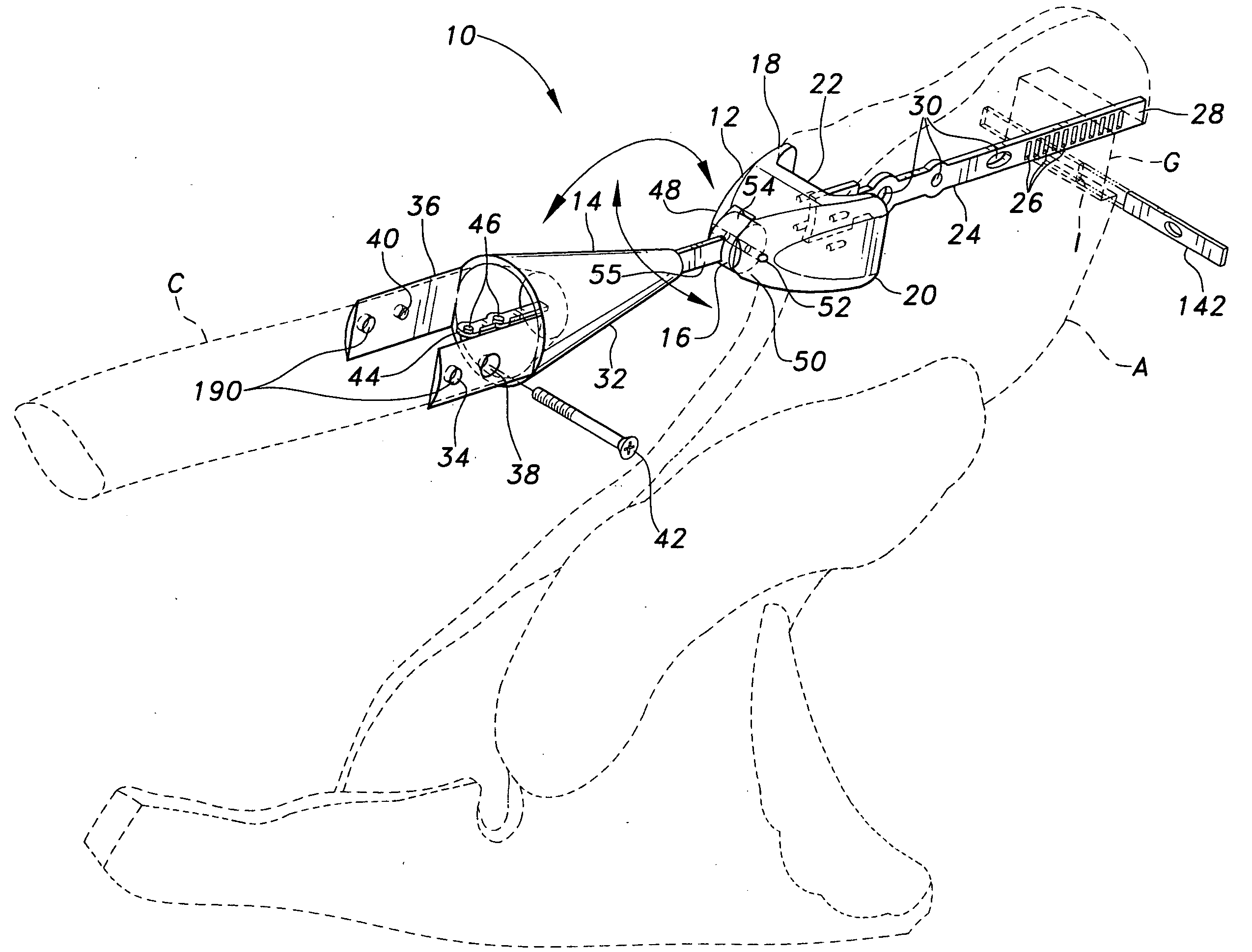
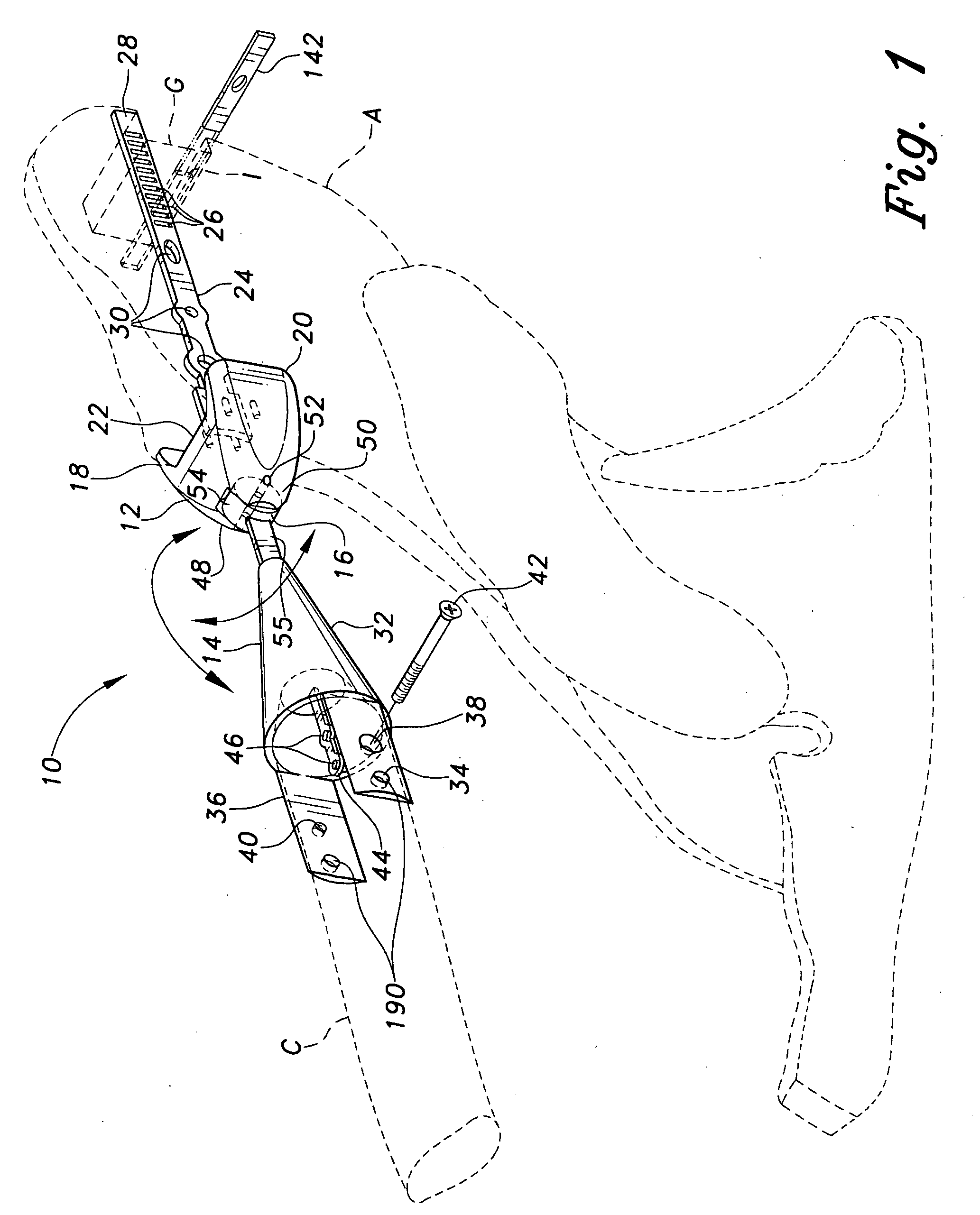
[0044] The present invention comprises a series of embodiments of an acromioclavicular joint prosthesis, serving to reconnect a separated or damaged joint between the acromion of the scapula and the clavicle. FIG. 1 of the drawings provides a front and top perspective view of the present prosthesis, designated by the reference numeral 10. The prosthesis 10 of FIG. 1 is relatively simple in comparison to other embodiments of the present invention, having only a single pivot point or hinge between the two attachment components to permit only one degree of freedom of motion between the two components. It will be seen that additional motion may be provided by including additional pivotal axes and / or telescoping mechanisms, as may be required or desired.

[0045] The acromioclavicular prosthesis 10 of FIG. 1 essentially comprises an acromion attachment component 12, a clavicle attachment component 14, and an articulated linkage 16 therebetween to connect the two components 12 and 14 to one ...

embodiment 100

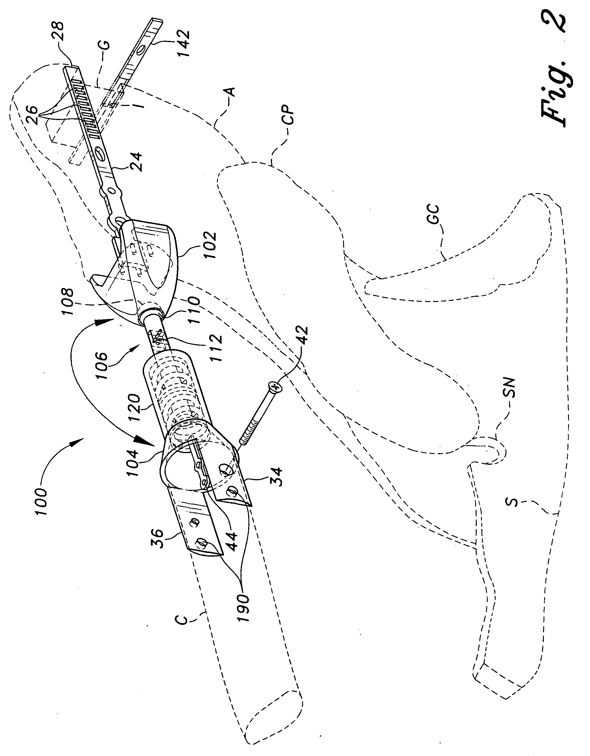
[0053]FIG. 5 provides a detailed top plan view in partial section of another resilient joint component for incorporation with the present acromioclavicular joint prosthesis, if so desired. A person having the present acromioclavicular prosthesis may occasionally encounter a sharp compressive blow to the shoulder, which could result in damage to the prosthesis. Accordingly, a linearly displaceable, spring-loaded fitting may be provided in the acromion attachment shock absorber body 120 of the prosthesis embodiment 100, if so desired. The component 120 acts somewhat as a shock absorber, as the name implies. A washer 132 or the like is immovably affixed to the shaft extension 134 which carries the tongue 122 of the breakaway fitting 112. Compression and extension springs 136 and 138 are assembled within the housing or body 120 on opposite sides of the washer 132.

[0054] A compression of the prosthetic joint 100 will cause the compression spring 136 to compress between the washer 132 and...

embodiment 10

[0070] Once the screw 42 has been tightened, the clamping tool 172 may be released from the clavicle C and the clavicle arm attachment ends 188 of the two tension rods 184 removed from the clavicle attachment component arms 36 and 38 to complete the installation. The completed installation of the acromioclavicular joint prosthesis 100 of the present invention is illustrated in FIG. 10 of the drawings. Other embodiments, e.g. the embodiment 10 of FIG. 1, will be seen to install in a similar manner as that described for the prosthesis 100. The result is a durable and reliable prosthetic joint serving to secure the distal or outboard end of the clavicle to the acromion process of the scapula, to repair or replace that joint which has been previously damaged due to injury or disease.


PUM


Abstract

The acromioclavicular joint prosthesis of the present invention provides a mechanism for securing the distal or outer end of the clavicle to the acromion of the scapula. The present prosthetic device includes an acromion attachment component, an opposite clavicle attachment component, and an articulated joint between the two components. The intermediate joint may include a “breakaway” component, allowing the joint to be temporarily misaligned in the event that a severe force is applied to the shoulder, rather than damaging the joint or shoulder structure. The breakaway joint may be quickly and easily realigned by a medical professional. The joint may also include a spring loaded shock absorption component as well, to avoid damage to the joint due to excessive tensile forces. Tools and a method for surgically installing and locking the present prosthesis securely to the respective bones of the skeletal structure, are also disclosed.

Description

BACKGROUND OF THE INVENTION [0001] 1. Field of the Invention [0002] The present invention relates generally to the medical and surgical fields, and more specifically to an internal prosthesis (endoprosthesis) for the shoulder joint between the acromion extension of the scapula and the outward end of the clavicle. The acromioclavicular joint prosthesis of the present invention serves to reconnect the two bones of this joint, while providing the freedom of movement and shock absorption required. [0003] 2. Description of the Related Art [0004] Shoulder injuries occur relatively frequently, and may comprise injury to any of a number of different joints and tissues. While a relatively simple dislocation of the ball of the upper arm bone (humerus) from its glenoid seat in the scapula is perhaps the most common shoulder injury, there are a large number of other injuries which can occur, from breakage of bones in the shoulder area to the tearing of ligaments and other tissues, damage to the...

Claims


Application Information

Patent Timeline
IPC IPC(8): A61F2/40A61F2/46
CPCA61F2/40A61F2/4612A61F2002/4088A61F2002/4628A61F2002/4623Y10S606/916A61F2002/4627A61F2002/4092A61F2/4603
Inventor NOVELLI, ANGELO
Owner NOVELLI ANGELO
Learn More