Integrated engine welder and electric compressor

a technology of electric compressor and engine, which is applied in the field of integrated engine welder and electric compressor, can solve the problems of limited position of compressor, and achieve the effect of convenient transportation

Active Publication Date: 2005-07-21
LINCOLN GLOBAL INC
View PDF26 Cites 51 Cited by
  • Summary
  • Abstract
  • Description
  • Claims
  • Application Information

AI Technical Summary

Benefits of technology

The present invention is a portable engine-powered welding and air compressor that can be easily moved to a welding site and operated by a user. The technical effect of this invention is that it provides a convenient and efficient solution for welding and operating air and electric tools, making the welding process easier and more flexible.

Problems solved by technology

The technical problem addressed in this patent text is the need for an integrated engine driven welder and compressor unit that can provide both electrical power and air pressure for use by various tools at a work site. The current units have limitations in terms of space and positioning, and can be more expensive than necessary. The solution is to design an integrated unit that allows for the air compressor to be ergonomically positioned within the housing of the engine welder, and simplifies the design and reduces manufacturing costs.

Method used


Image

  • Integrated engine welder and electric compressor
  • Integrated engine welder and electric compressor
  • Integrated engine welder and electric compressor

Examples


Embodiment Construction

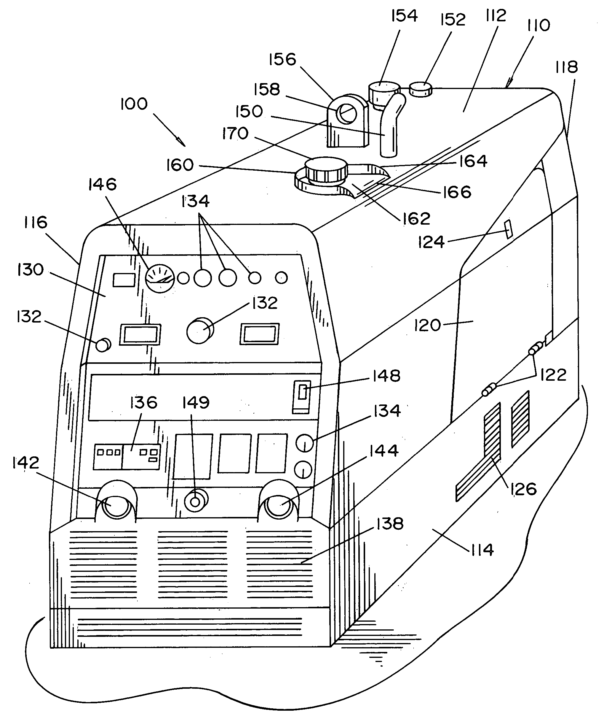
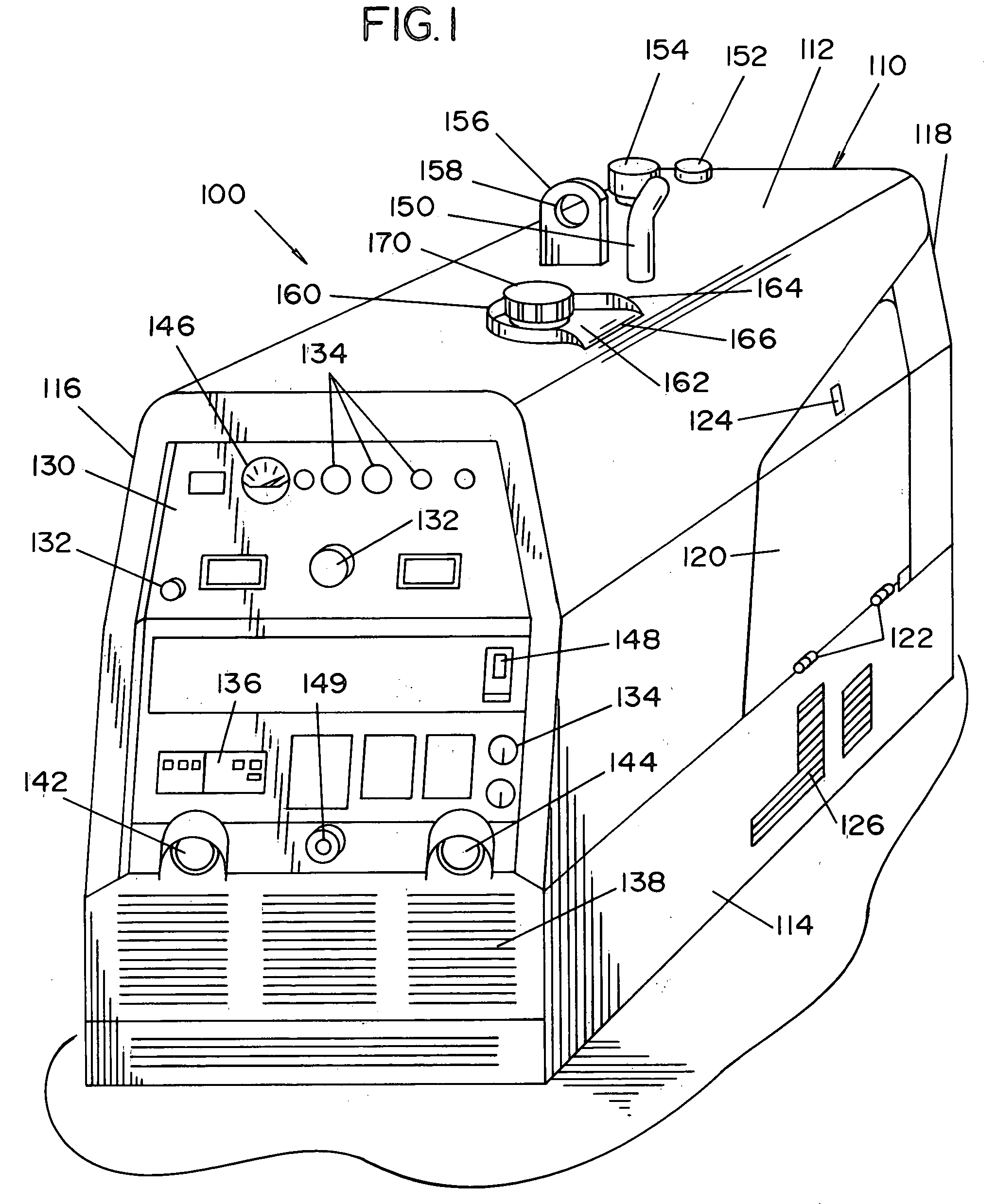
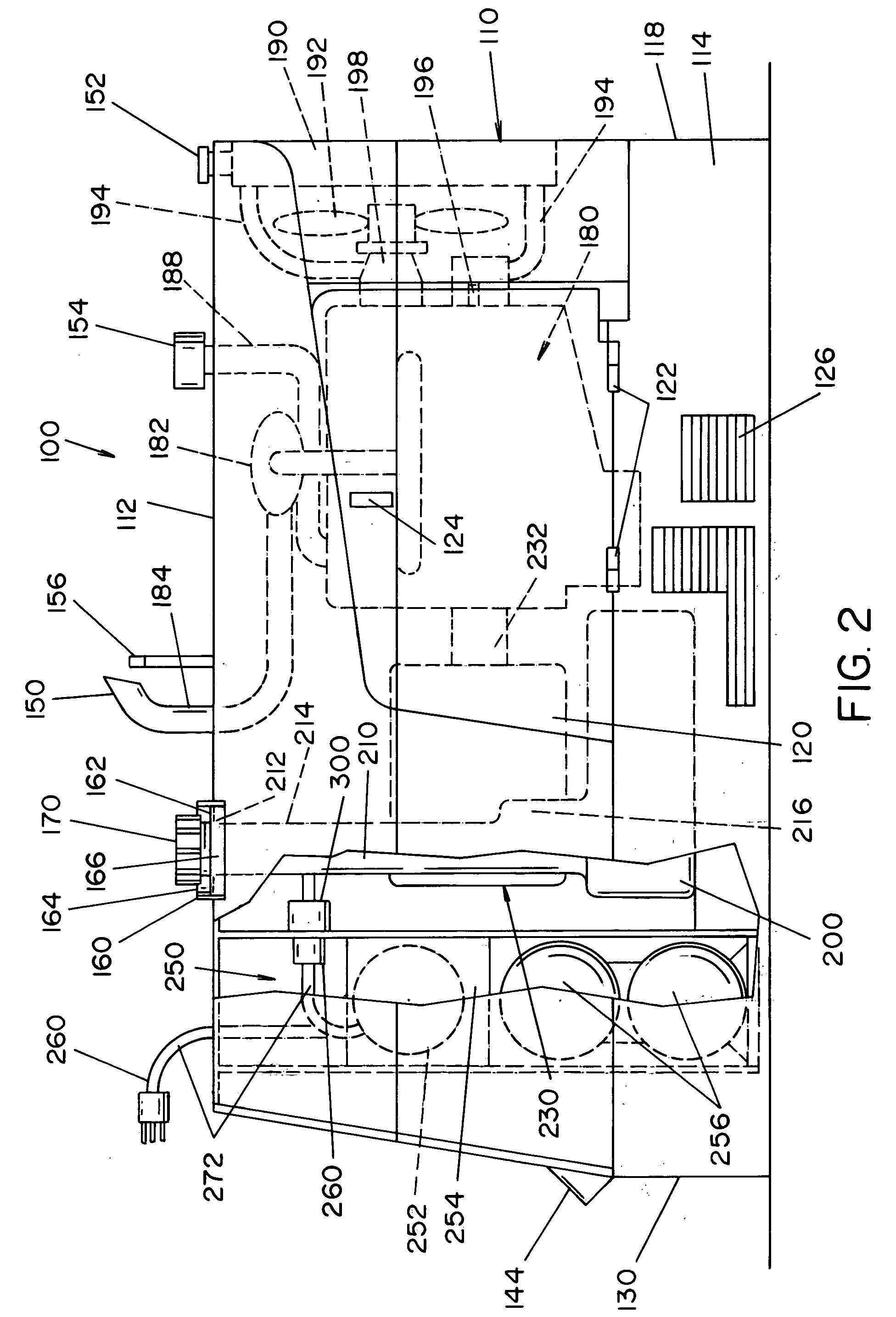
[0034] Referring now to the drawings, wherein the showings are for the purpose of illustrating the preferred embodiments of the invention only and not for the purpose of limiting the same, FIGS. 1-3 illustrate one embodiment of the invention. Specifically, these figures illustrate a self-contained, portable and fully-integrated welder / generator and compressor unit 100 in accordance with the present invention. Unit 100 includes a housing 110 that having a top portion 112, two side portions 114, 116, a back side 118 and a front panel 130. The welding housing is designed to encase at least a portion of the internal components of the engine welder. Positioned in the top portion 112 of welding housing 110 is an exhaust pipe 150. The top of the housing typically includes one or more fluid accesses 152, 154 to add coolants, lubricants, etc. to the engine located in the housing. The top of the housing also typically includes a lift device 156 having an opening 158. The lift device is used t...


PUM

PropertyMeasurementUnit
Pressureaaaaaaaaaa
Poweraaaaaaaaaa
Currentaaaaaaaaaa

Abstract

An integrated welder, generator and compressor unit that includes a housing that at least partially contains components of a welder, generator and an electric compressor. An engine, an electric current generator, and an electric air compressor are at least partially mounted in the housing. The electric current generator is at least partially connected to the engine to be at least partially driven thereby. The electric air compressor can be at least partially powered by the electric current generator during the operation of the engine. Alternatively, the air compressor can be powered by an external source of power without the use of the engine/generator.

Description


Claims


Application Information

Patent Timeline
Owner LINCOLN GLOBAL INC
Why Eureka
Try Eureka