Stationary soap dispenser assembly

a soap dispenser and assembly technology, applied in the direction of washstands, liquid handling, instruments, etc., can solve the problems of creating unsanitary conditions, unappealing soap dispenser appearance, and unappealing dispenser design

Active Publication Date: 2005-07-21
DELTA FAUCET COMPANY
View PDF47 Cites 30 Cited by
  • Summary
  • Abstract
  • Description
  • Claims
  • Application Information

AI Technical Summary

Problems solved by technology

By using a moveable head, the appearance of the soap dispenser can be aesthetically unappealing.
Many factors make this type of dispenser design unappealing, such as large gaps as well as visual steps formed between the dispensing head and base of the dispenser.
Since the soap is dispensed from the head, the moveable head creates a moving target from which the soap is dispensed, and this moving target in turn can create unsanitary conditions.
For example, as the head moves in a downward direction, the outlet of the dispenser can come into contact with dirt from the hands being cleaned, and during an upstroke of the head, the dirt can be sucked up into the dispenser, so that the inside of the dispenser becomes contaminated.
To alleviate concerns about theft of the soap dispenser, the soap dispenser is permanently mounted to the countertop, thereby making removal of the soap dispenser from the countertop rather difficult.
As should be appreciated refilling such dispensers can be cumbersome, and as a result, many soap containers are not refilled or are only refilled on a sporadic basis.
Another concern with fixed soap dispensers is that due to their fixed nature, the soap dispenser can be difficult to clean.
Typically, these openings are covered with a cap that some consider aesthetically unappealing or even ugly, because they fail to provide a clean look to the sink.
However, since the decorative objects are not secured, they can easily fall into the sink or onto floor, thereby creating safety concerns.
Typical soap dispenser are utilitarian in nature and do not allow flexibility in providing a wide range of appearances, that is the outside appearance of the dispenser is highly dependent on the structure of the pump mechanism contained in the dispenser.
Over time styles of soap dispensers can become dated, but their designs are not changed, due to the prohibitive costs involved in redesigning the dispenser and retrofitting equipment.

Method used


Image

  • Stationary soap dispenser assembly
  • Stationary soap dispenser assembly
  • Stationary soap dispenser assembly

Examples


Embodiment Construction

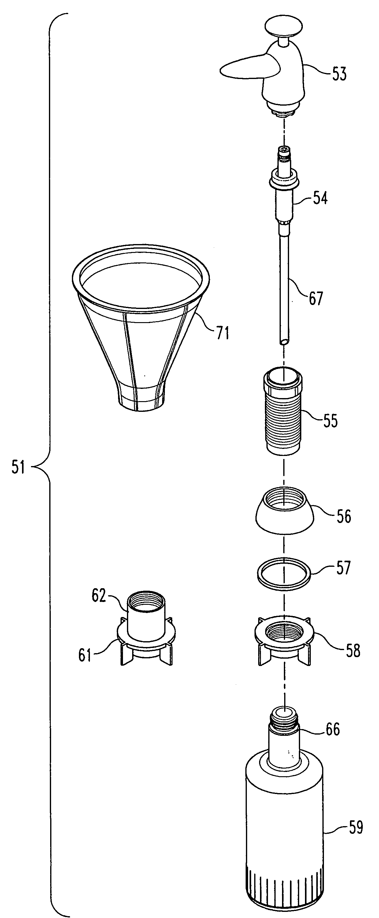
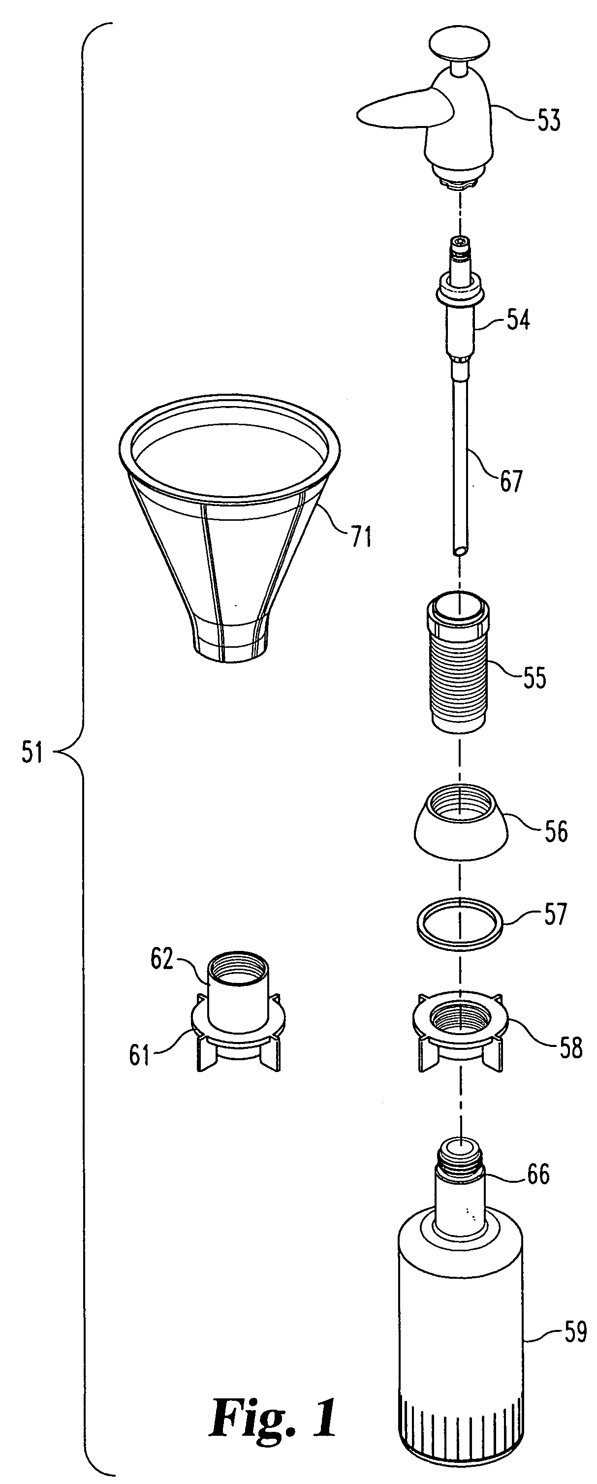
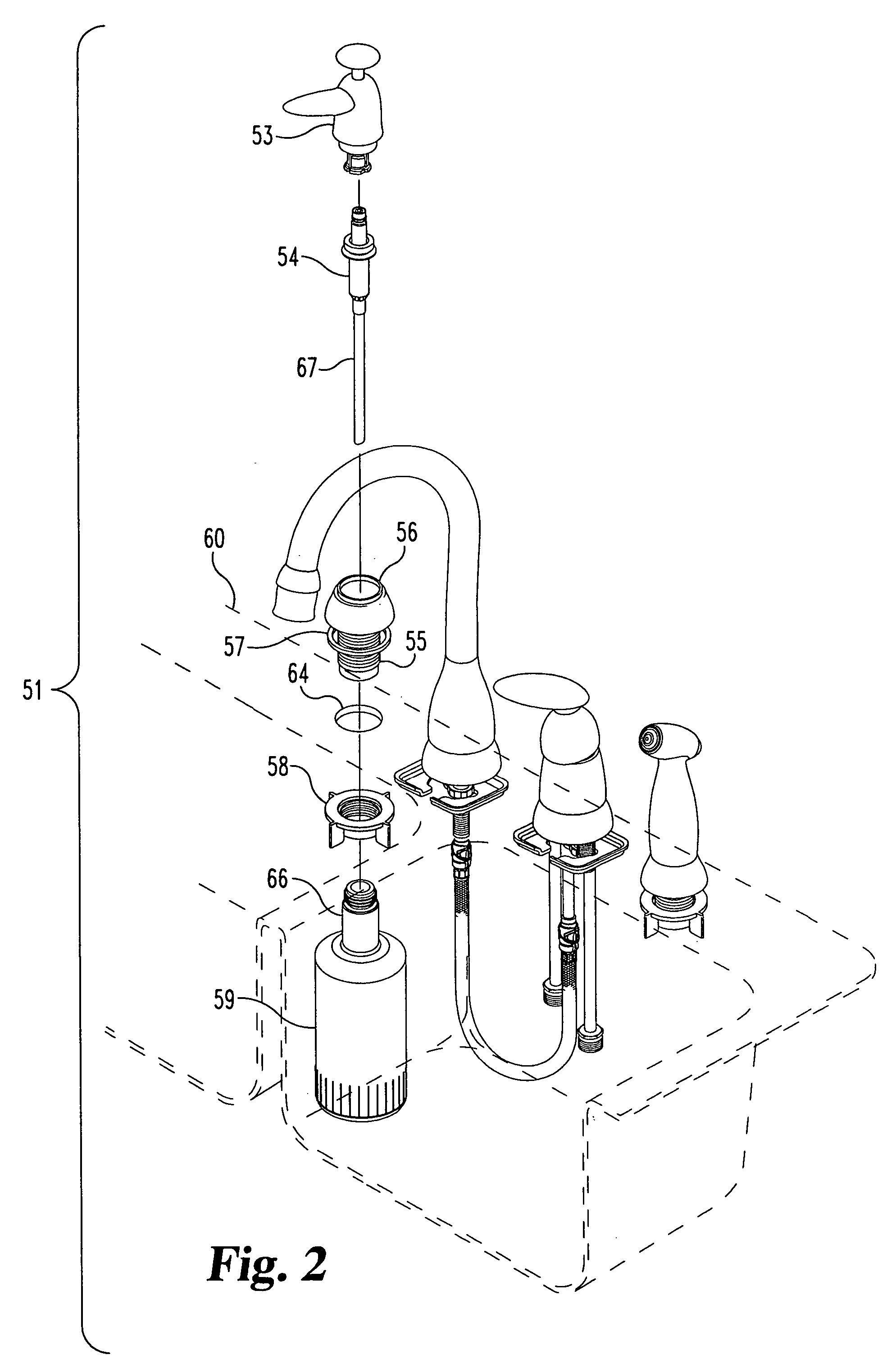
[0045] For the purpose of promoting an understanding of the principles of the invention, reference will now be made to the embodiments illustrated in the drawings and specific language will be used to describe the same. It will nevertheless be understood that no limitation of the scope of the invention is thereby intended. Any alterations and further modifications in the described embodiments, and any further applications of the principles of the invention as described herein are contemplated as would normally occur to one skilled in the art to which the invention relates. One embodiment of the invention is shown in great detail, although it will be apparent to those skilled in the relevant art that some features that are not relevant to the present invention may not be shown for the sake of clarity.

[0046] A fluid dispenser assembly or kit 51, according to one embodiment (among others) of the present invention, will initially be described with reference to FIGS. 1 through 7. The fl...


PUM


Abstract

A fluid dispenser system includes a container that is mounted below a mounting surface for containing a fluid. A base is mounted above the mounting surface, and the base defines an opening configured to allow passage of the fluid when filling the container. A dispenser body is detachably coupled to the base to allow removal of the dispenser for filling the container with the fluid from above the mounting surface. The dispenser body has a moveable handle that is moveable for manually pumping the fluid and a fixed spout that is fixed in position relative to the mounting surface when the fluid is dispensed from the spout.

Description

REFERENCE TO RELATED APPLICATIONS [0001] The present application claims the benefit of U.S. Provisional Patent Application No. 60 / 537,450, filed Jan. 16, 2004, which is hereby incorporated by reference in its entirety.BACKGROUND [0002] The present invention generally relates to fluid dispensers, such as liquid soap dispensers, and more specifically, but not exclusively, concerns a manually operated liquid soap dispenser with an outlet that remains generally stationary during dispensing of liquid soap and allows the soap to be refilled from the top of a countertop. [0003] Typical soap dispensers utilize a decorative head assembly that is attached to the pump. In order to dispense fluid, such as liquid soap, the entire head assembly moves downwardly and upwardly in a telescoping fashion as the pump is actuated. By using a moveable head, the appearance of the soap dispenser can be aesthetically unappealing. Many factors make this type of dispenser design unappealing, such as large gaps...

Claims


Application Information

Patent Timeline
Patent Type & Authority Applications(United States)
IPC IPC(8): B67D7/06A47K1/08A47K5/12B67D7/58G01F11/02
CPCA47K1/08G01F11/021A47K2005/1218A47K5/1205
Inventor MEEHAN, STEVEN KYLECROWE, DARRELL SCOTTNELSON, ALFRED C.
Owner DELTA FAUCET COMPANY
Why Eureka
Try Eureka