Right angled connector

Inactive Publication Date: 2005-07-21
OSRAM SYLVANIA INC
View PDF8 Cites 2 Cited by
  • Summary
  • Abstract
  • Description
  • Claims
  • Application Information

AI Technical Summary

Benefits of technology

[0005] Still another object of the invention is to reduce the number of parts for an electrical connector.
[0009] The construction thus described provides a connector that comprises only three parts and all of the insulating parts are constructed as a single body. The connector is rigid, easily passing the required bending forces test and is economical to manufacture and assemble.

Problems solved by technology

These connectors have worked well in the past; however, they were expensive because of the number of parts they entailed.
Often, the interface of the cover to the bracket will fail before the required forces are met.
It is believed that this failure occurs because to the difficulty in maintaining critical tolerances between the multiple parts.

Method used


Image

  • Right angled connector
  • Right angled connector
  • Right angled connector

Examples


Embodiment Construction

[0013] For a better understanding of the present invention, together with other and further objects, advantages and capabilities thereof, reference is made to the following disclosure and appended claims in conjunction with the above-described drawings.

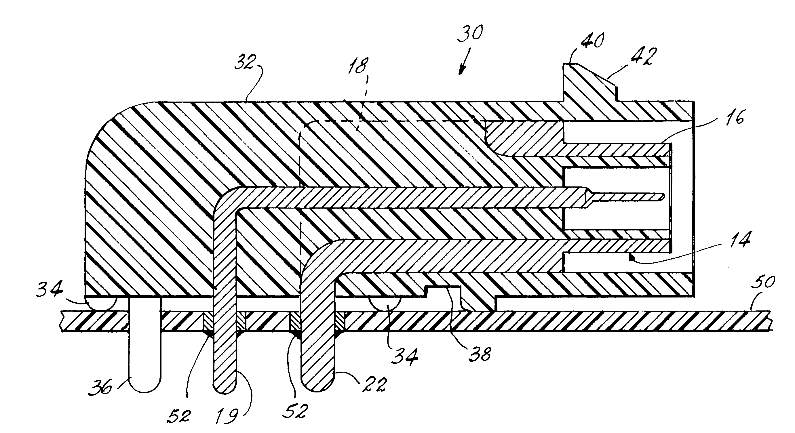
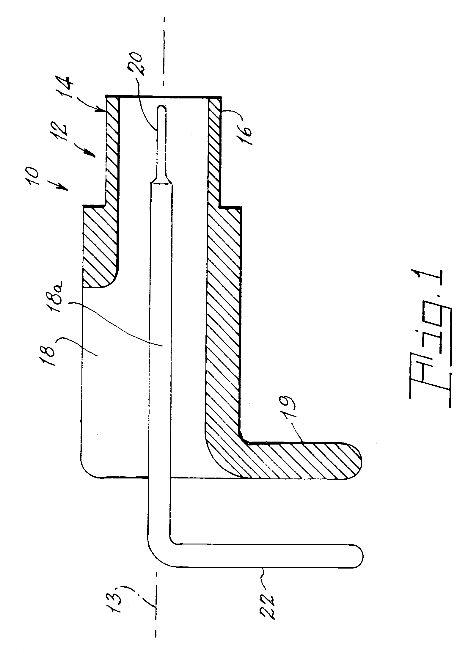
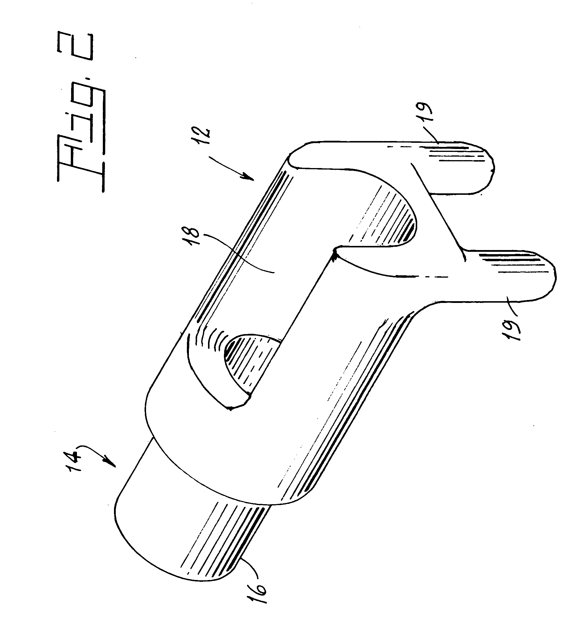
[0014] Referring now to the drawings with greater particularity, there is shown in FIG. 1 a subassembly of a right-angled electrical connector. Specifically, a right-angled connector in accordance with an aspect of the invention comprises a subassembly 10 having an electrically conductive member or ground shell 12 having a longitudinal axis 13 with at least a portion 14 of the member 12 providing a cylindrical, hollow end 16. A trough 18 is formed in the member 12 to accommodate an electrically conductive contact pin 18a and at least one leg 19 is provided on member 12 extending in a direction transverse to the longitudinal axis 13. In a preferred embodiment of the invention the member 12 has two legs, 19, as shown in FIG. 2, which, ...


PUM


Abstract

A right-angled electrical connector (30) has a one-piece electrically insulating body (32) molded over a subassembly (10) that includes a first electrically conductive member 12 with a hollow end (16) and an electrical contact (18a) mounted within the hollow end (16). In the mold the contact pin (18a) is electrically isolated from the member (12) and electrically insulating material of the body 32 flows around the contact pin (18a).

Description

TECHNICAL FIELD [0001] This invention relates to electrical connectors and more particularly to such connectors for receiving a coaxial cable contact. Still more particularly, it relates to right angle connectors for use with printed circuit boards. BACKGROUND ART [0002] Electrical connectors, particularly right angled connectors for attachment to printed circuit boards (hereafter, PCB or PCBs) for receiving coaxial cable contacts, for example, for connecting automotive radio antennas, are known. These connectors have worked well in the past; however, they were expensive because of the number of parts they entailed. Such connectors are shown, for example, in U.S. Pat. No. 6,386,888. This latter connector comprises a metal bracket, a metal shell, a plastic insulator, a plastic cover and a contact. While this connector works well under normal conditions, test requirements for this connector require that it be plugged into a mating connector on a coaxial cable. This mating connector's ...

Claims


Application Information

Patent Timeline
IPC IPC(8): H01R12/00
CPCH01R24/50H01R12/727H01R2201/02H01R2103/00
Inventor SWANTNER, MICHAEL J.BROWN, SHANESEYMOUR, DOUGLAS G.
Owner OSRAM SYLVANIA INC
Why Eureka
Try Eureka