Child resistant container-closure assembly

a container and latching technology, applied in the direction of caps, sealing, liquid handling, etc., can solve the problems of unfavorable impact on the child-resistant feature of the assembly, the number of embodiments is rather complicated and expensive to manufacture, and the tensile strength of the assembly tends to lose, so as to achieve economic effect of manufacturing

Inactive Publication Date: 2008-12-30
KRUEGER DAVID
View PDF14 Cites 7 Cited by
  • Summary
  • Abstract
  • Description
  • Claims
  • Application Information

AI Technical Summary

Benefits of technology

[0010]With the foregoing in mind, it is an object of the present invention to provide a child resistant container-closure system which is relatively economical to manufacture and assemble and is extremely effective for the purposes intended. Accordingly, the present invention is characterized by novel features of construction and arrangement providing safety to children and yet can be easily manipulated to open and close to access the container by the aged and infirm.
[0013]Thus, the present invention essentially provides a system comprising cooperative elements formed integrally with the cap and container, one of which is flexible to provide a positive consistent uniform biasing force to retain the cap in a locked, child resistant position instead of the prior art systems which utilize a liner subject to permanent deformation over a period of use which may adversely effect the child resistant aspect of the system. Further, the system of the present invention is economical to manufacture and is totally reliable over the life of the container closure.

Problems solved by technology

For example, it has been found that over a period of use, the liner tends to lose some of its resiliency and this unfavorably impacts the child resistant feature of these assemblies.
Furthermore, a number of the embodiments are rather complicated and expensive to manufacture.

Method used


Image

  • Child resistant container-closure assembly
  • Child resistant container-closure assembly
  • Child resistant container-closure assembly

Examples


Embodiment Construction

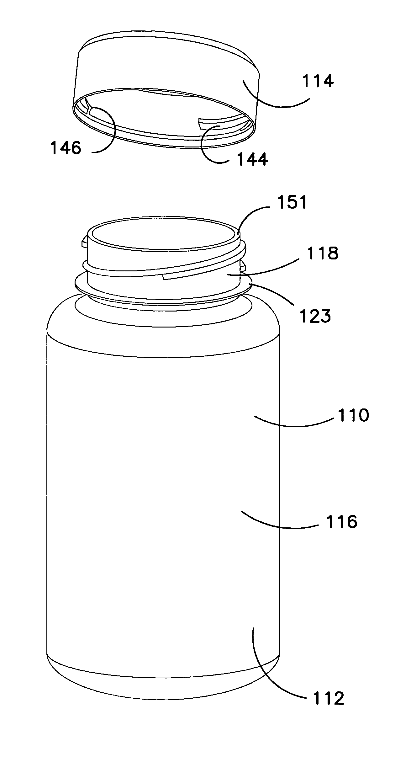
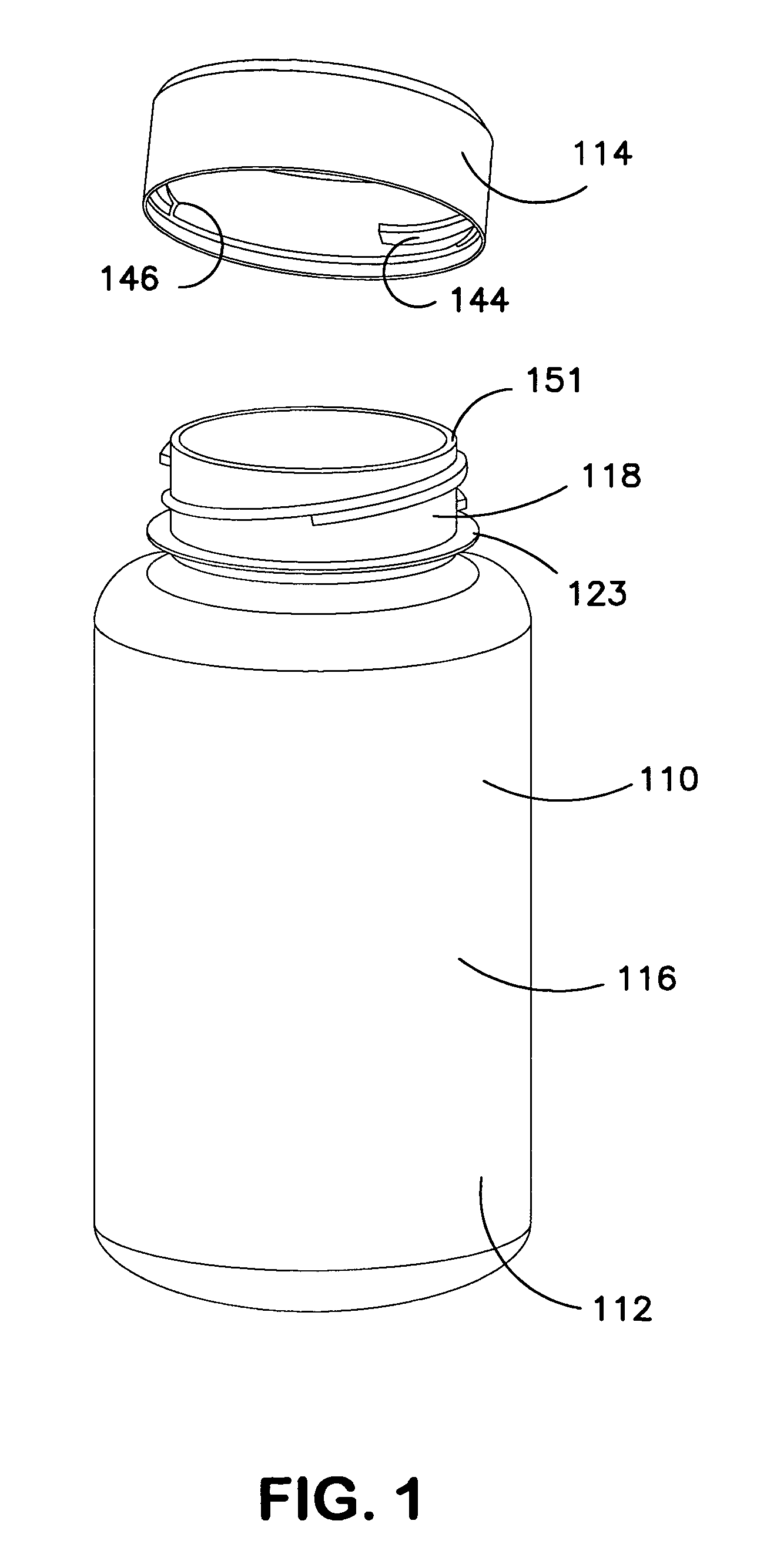
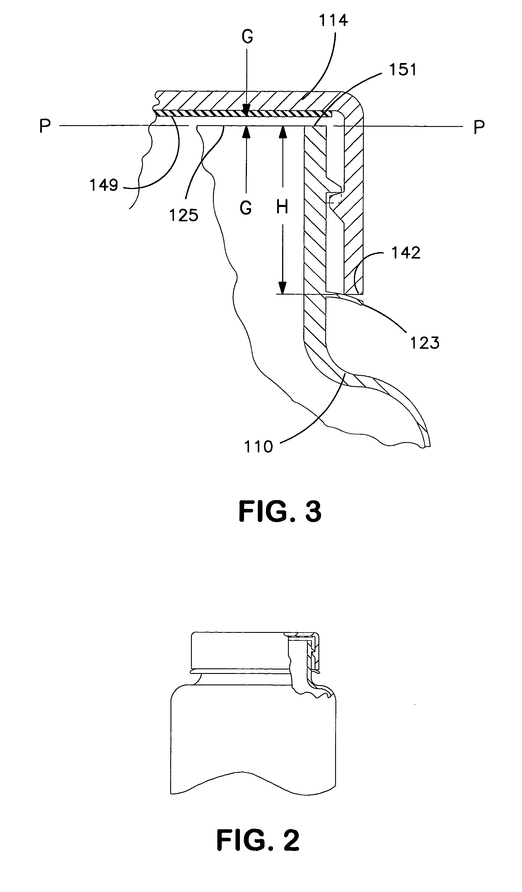
[0035]Referring now to the drawings and particularly to FIG. 1 thereof, there is shown a first embodiment of child resistant container-closure assembly in accordance with the present invention generally designated by the numeral 110. The assembly comprises a container 112 and cap 114 which may be molded of a suitable plastic material.

[0036]The container 112 has a body portion of generally cylindrical cross section and an upstanding neck portion or bottle finish 118 of smaller diameter. The exterior of the bottle finish 118 has spiral splines, in the present instance, two spline segments 120 and 122. The spline segments 120, 122 extend about half way around the neck of the bottle and each has an enlarged portion 120a, 122a and a cutback portion 120b defining a step configuration and detents 124 and 126 approximately midway of the segments. In accordance with this embodiment of the invention, a circumferentially extending flexible flange 123 extends radially outwardly from the bottle ...


PUM


Abstract

A container closure assembly comprising a container having a finish and external threads and a cup-like cap having a top and a depending circumferentially extending skirt having second internal threads engagable with the container threads. Detents are providing on one of said threads to normally prevent rotation of the cap in a direction to remove it from the container. First and second interengaging members are formed integrally with the cap and container. One of the interengaging members is flexible to bias the cap in an upward direction to maintain the threads in engagement when the cap is seated on the container. Displacement of the cap downwardly against the normal bias of the interengaging means displaces the cap and container threads to disengage the detents to permit rotation of the cap in a direction to remove it from the container.

Description

FIELD OF THE INVENTION[0001]The present invention relates to child resistant tamper evident closure assemblies and more specifically to a novel improvement in assemblies of this type which is easy and economical to manufacture and truly effective for the purposes intended.BACKGROUND OF THE INVENTION[0002]Child resistant tamper proof container-closure assemblies are not new per se. For example, in U.S. Pat. No. 3,888,376 entitled SAFETY CLOSURE CAP FOR CONTAINERS, the cap has a depending skirt having internal spiral threads which cooperate with threads on the bottle finish to permit application and removal of the cap. The threads have inter-engaging shoulders which permit rotation of the cap to apply it to the container and interengage to normally lock the container against rotation in a direction to remove it. The cap has a resilient liner so that when it is desired to remove the cap, the user applies a downward force against the top compressing the resilient liner and moving the ca...

Claims


Application Information

Patent Timeline
Patent Type & Authority Patents(United States)
IPC IPC(8): B65D55/02
CPCB65D50/043B65D2215/02
Inventor KRUEGER, DAVID
Owner KRUEGER DAVID
Why Eureka
Try Eureka