
Packet shaper

a shaper and packaging technology, applied in the field of packaging shapers, can solve the problems of inability to achieve high-speed shaping, and inability to shape related art shapes

Inactive Publication Date: 2005-07-28
ALAXALA NETWORKS
View PDF9 Cites 61 Cited by
  • Summary
  • Abstract
  • Description
  • Claims
  • Application Information

AI Technical Summary

Benefits of technology

The present invention proposes a packet shaper that can efficiently shape traffic to multiple users while ensuring that important packets are prioritized and not discarded. The packet shaper uses a priority decision system to decide which packets should be sent out from a shared buffer, based on their importance to the user. This allows users to make efficient use of the available bandwidth and ensures secure transmission of important packets. The technical effects of the invention include high-speed shaping and efficient use of minimum bandwidth with secure transmission of important packets.

Problems solved by technology

The previous packet shapers of related art have two problems.
The first problem is that high-speed shaping is impossible when the number of users increases.
Because time to decide what queue from which a packet is sent out increases as the number of users increases, high-speed shaping cannot be expected when the shaper serves traffic to many users.
The second problem is that users cannot make efficient use of minimum bandwidth.
As described above, it was impossible for the packet shapers of prior art to perform high-speed shaping, while ensuring the transmission of packets to many users within user-specific minimum bandwidth.
Furthermore, the packet shapers of prior art were not designed for efficient use of minimum bandwidth with secure transmission of important packets, resulting in that users could not make efficient use of minimum bandwidth.

Method used


Image

  • Packet shaper
  • Packet shaper
  • Packet shaper

Examples


Embodiment Construction

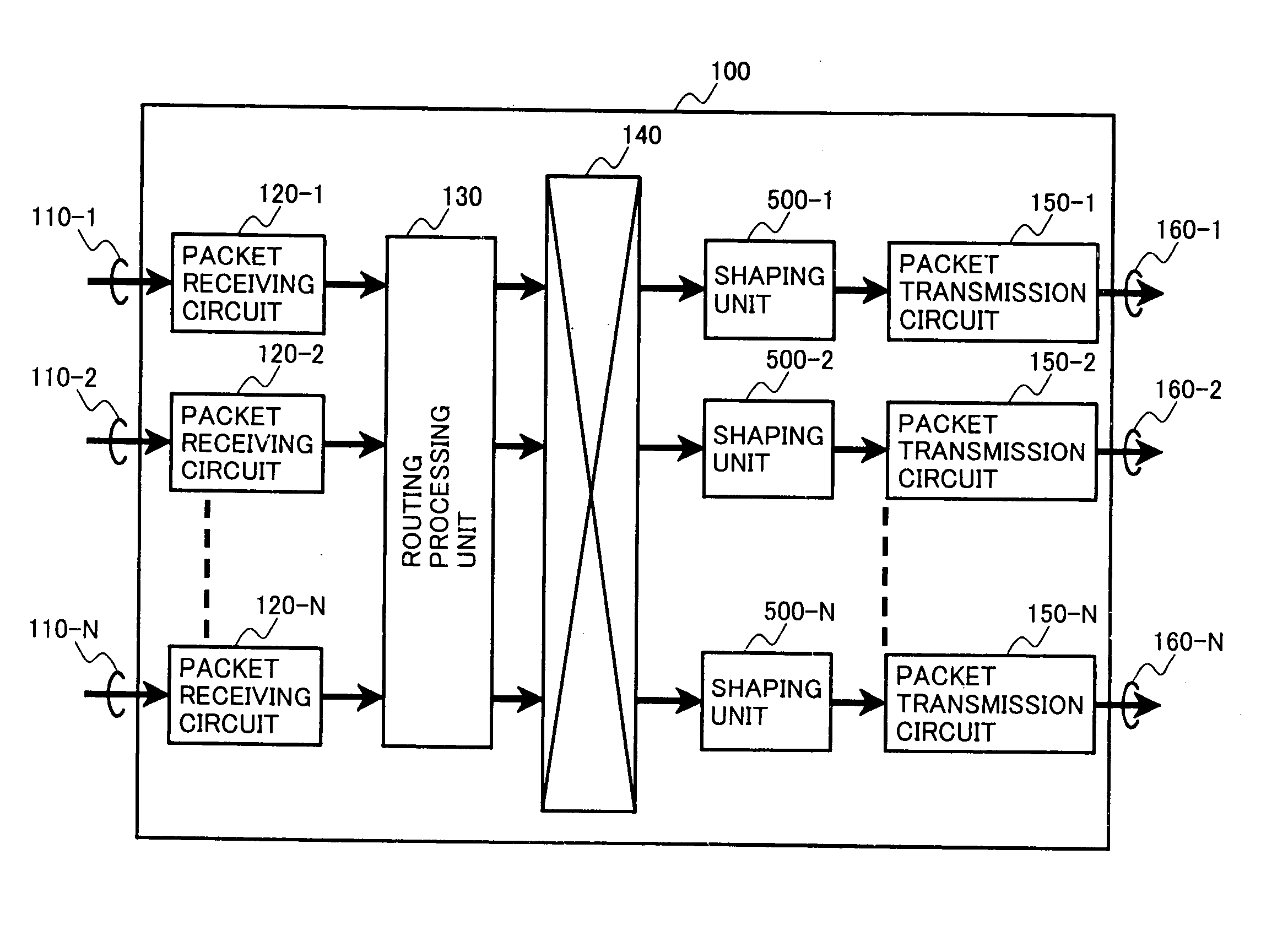
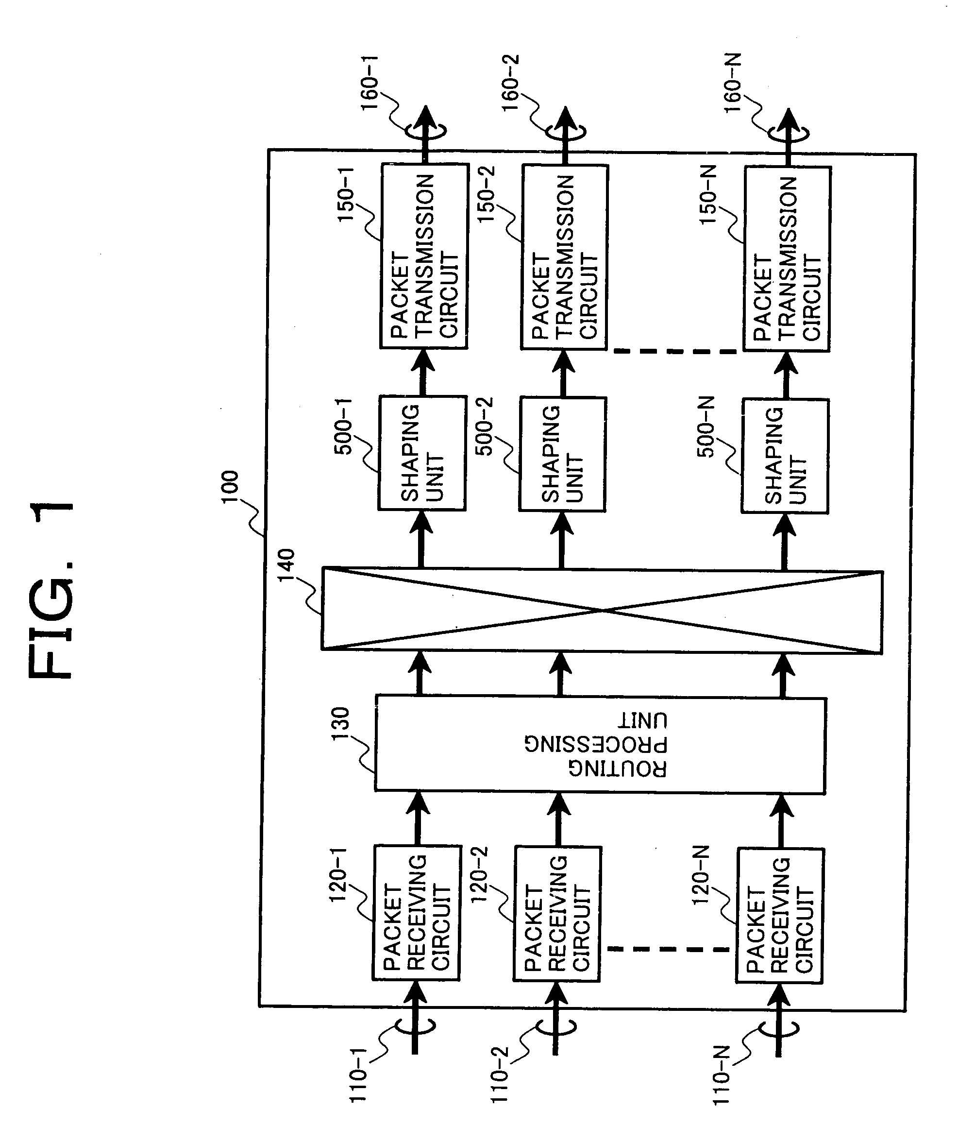
[0030] First, the outline operation of a router that is capable of packet shaping by the present invention will be explained with reference to FIGS. 1 to 4. FIG. 1 shows a router 100 to which the present invention is applied. The router 100 consists of N pieces of incoming lines 110-i (where i=1 to N) through which packets are input to the router, packet receiving circuits 120-i that execute packet reception processing, a routing processing unit 130, a packet switching means 140 that executes switching of packets, shaping units 500-j (where j=1 to N), each provided for each output line, packet transmission circuits 150-j that execute transmission processing, and N pieces of output lines 160-j across which packets are sent out.

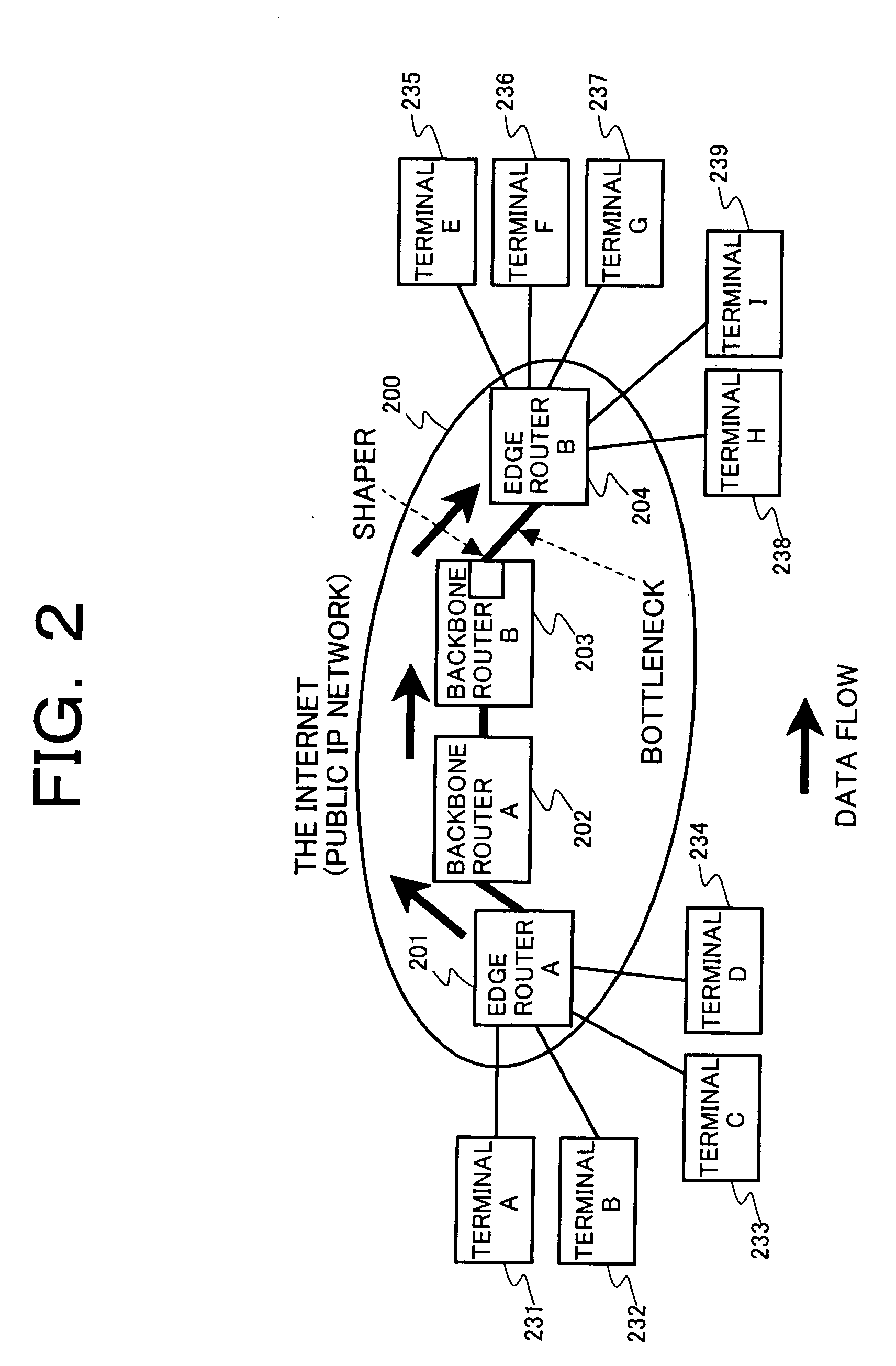
[0031]FIG. 3 shows an example of the format of a packet to be transmitted across an internet 200. The packet to be transmitted across the internet 200 consists of a header unit 310 and a data unit 320. The header unit essentially contains a Source IP Address (...


PUM


Abstract

When a packet arrives at a shaping unit 500, a discard control unit 510 judges whether to “store” or “discard” the arrived packet. Packets judged to be “stored” are stored into a packet storage FIFO buffer 520 and sent out within a transmission bandwidth greater than the total sum of user-by-user minimum bandwidths. A bandwidth check unit 600 checks bandwidth per user and judges packets that fall within the bandwidth to be high priority packets and packets that fall outside the bandwidth to be low priority packets. If a large quantity of packets are stored into the packet storage FIFO buffer 520, the discard control unit 510 determines that low priority packets are exclusively “discarded,” thus securing high priority packets from being discarded. Thereby, the shaping unit 500 ensures proper packet transmission within user-specific minimum bandwidth.

Description

[0001] The present application is a continuation of application Ser. No. 09 / 811,504, filed Mar. 20, 2001, the contents of which are incorporated herein by reference.BACKGROUND OF THE INVENTION [0002] The present invention relates to packet shapers that shape packets to transmission bandwidth. [0003] In a packet mode communication method used for internets, because packets from many users can be transmitted in common over a same transmission line, the transmission cost per bandwidth can be decreased. Meanwhile, internet users have made a demand that Quality of Service (QoS) such as reduced delay time and a low packet discard rate that were implemented for conventional telephone networks and corporate private networks should also be implemented in internet operation. [0004] Guaranteed minimum bandwidth service, one QoS implementation service, is such that the carrier guarantees packet transmission within minimum bandwidth assigned by contract to each user (contractor with the carrier)...

Claims


Application Information

Patent Timeline
Patent Type & Authority Applications(United States)
IPC IPC(8): H04L47/32H04L47/6275
CPCH04L49/505H04L47/10H04L47/20H04L47/32H04L47/24H04L47/2441H04L47/29H04L47/22
Inventor YAZAKI, TAKEKIAIMOTO, TAKESHI
Owner ALAXALA NETWORKS
Features
  • Generate Ideas
  • Intellectual Property
  • Life Sciences
  • Materials
  • Tech Scout
  • Unparalleled Data Quality
  • Higher Quality Content
  • 60% Fewer Hallucinations
Learn More