Display control device, display control method, computer product

a display control device and display control technology, applied in the field of shifting display screens, can solve the problems of not being able to function as an instruction for the display screen to scroll, the location of the pen input device cannot be determined, and the relative difficulty of the screen shifting by the pen input device compared to the mous

Inactive Publication Date: 2005-08-04
FUJITSU LTD
View PDF7 Cites 49 Cited by
  • Summary
  • Abstract
  • Description
  • Claims
  • Application Information

AI Technical Summary

Benefits of technology

[0010] It is an It is an object of the present invention...

Problems solved by technology

However, when a screen area wider than the width of the screen display area is to be displayed in a display device, it is relatively more difficult to instruct the screen to shift by the pen input device as compared to a mouse.
However, the location of the pen input device cannot be determined unless the pen input devices touches the display screen.
Moreover, since touching the display screen with the pen input device is considered as an instruction for the computer, it cannot function as an instruction for the display screen t...

Method used


Image

  • Display control device, display control method, computer product
  • Display control device, display control method, computer product
  • Display control device, display control method, computer product

Examples


first embodiment

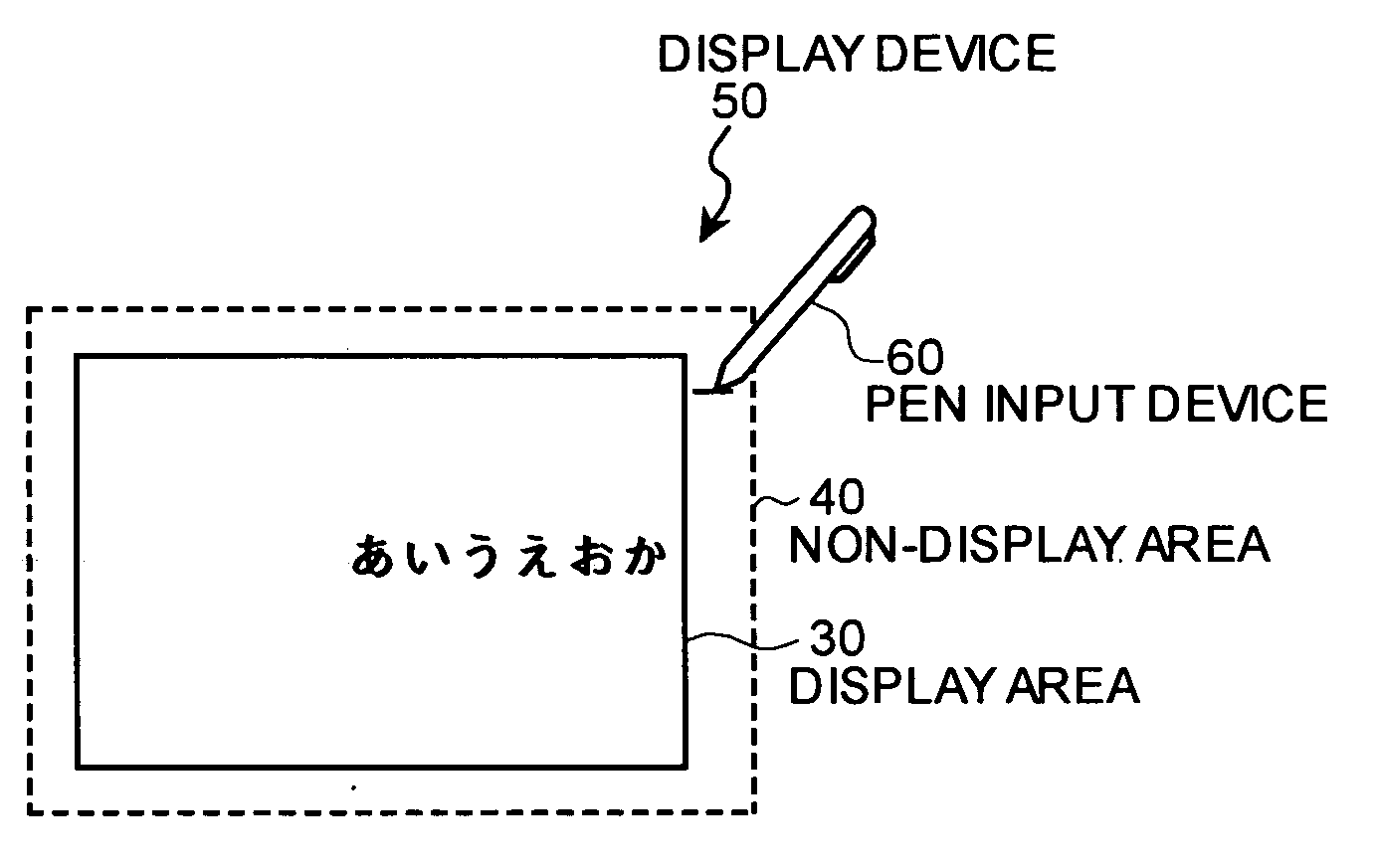
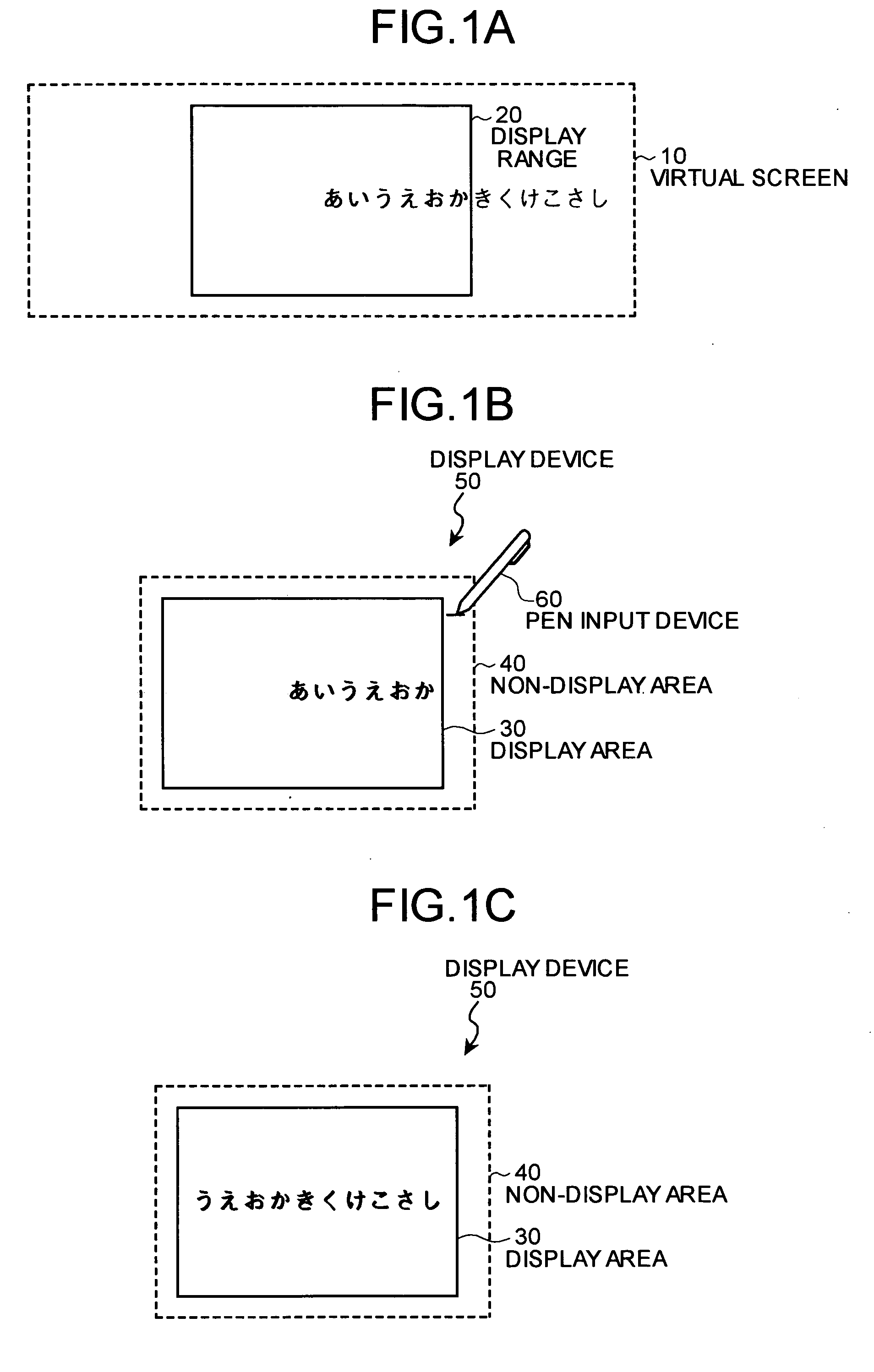
[0023] Thus, in the first embodiment, in addition to the display area 30, the display device 50 includes a pen input receiving area surrounding the display area 30, the margin between the pen input receiving area and the display area 30 comprising the non-display area 40, and the display screen is made to scroll by means of the pen input device 60 by dragging it in the non-display area 40 based on where the line is drawn as well as the direction in which the line is drawn, thereby enabling the scrolling of the screen by means of the pen input device 60.

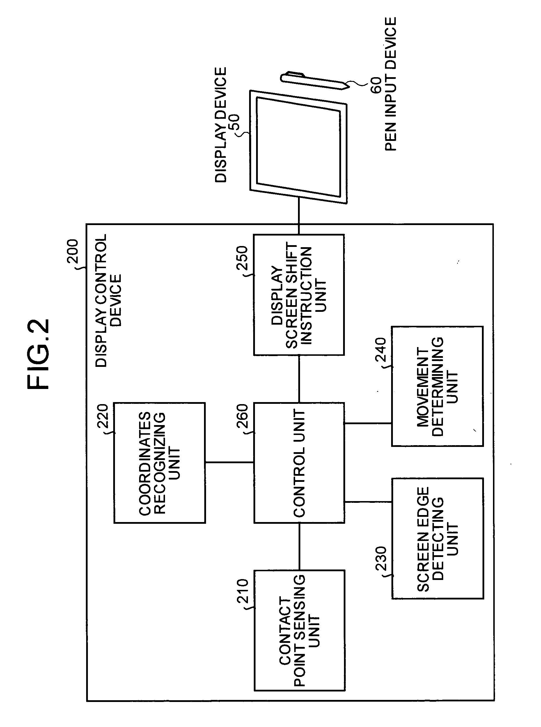
[0024] A configuration of a display control device according to the first embodiment is explained next. FIG. 2 is a functional block diagram of the display control device according to the first embodiment. As shown in FIG. 2, a display control device 200 includes a contact point sensing unit 210, a coordinates recognizing unit 220, a screen edge detecting unit 230, a movement determining unit 240, a display screen shift instruction un...

second embodiment

[0050] A display control process of the display control device 400 is explained next. FIG. 5 is a flowchart of the display control process of the display control device 400 according to the

[0051] As shown in FIG. 5, when the screen edge detecting unit 430 detects the contact of the pen input device 60 with the non-display area 40 (step S501), the display control device 400 determines whether the detected contact point is to the left, right, above, or below of the display area 30 (step S502), and determines the direction of shift of the display screen.

[0052] If the contact point is above the display area 30, the display screen shift instruction unit 450 instructs the display device 50 to shift the display screen downward by a predetermined distance (step S503). If the contact point is below the display area 30, the display screen shift instruction unit 450 instructs the display device 50 to shift the display screen upward by a predetermined distance (step S504). If the contact point...


PUM


Abstract

A display control device controls a display device that displays a screen area wider than a screen display area. The display control device includes a non-display area in the surrounding part of the screen display area, that receives pen input, but does not display the screen; a screen edge detecting unit that detects the touching of the non-display area by the pen; a movement determining unit that determines whether to start scrolling the display screen in a specific direction or whether to stop the scrolling based on whether the pen is touched in the non-display area, the direction of movement, and the amount of movement of the pen, and a display screen shift instruction unit that instructs the display device to start or stop scrolling the display screen.

Description

BACKGROUND OF THE INVENTION [0001] 1) Field of the Invention [0002] The present invention relates to a technology for shifting display screens. [0003] 2) Description of the Related Art [0004] Conventionally, a pen input device is generally used as an input device of a portable information terminal. Unlike a keyboard or a mouse, the pen input device is simple to operate and is portable and is best suited for the portable information terminal. In recent years, the pen input device is also used as the input device for tablet type personal computers with emphasis on simplicity of operations and portability. [0005] However, when a screen area wider than the width of the screen display area is to be displayed in a display device, it is relatively more difficult to instruct the screen to shift by the pen input device as compared to a mouse. [0006] For example, according to a technology disclosed in Japanese Patent Laid-Open Publication No. H6-348251, when the cursor location of the mouse m...

Claims


Application Information

Patent Timeline
IPC IPC(8): G09G5/00G09G5/08
CPCG06F3/04883G06F3/0485
Inventor OBITSU, TOSHIROHIGUCHI, HISAMICHI
Owner FUJITSU LTD
Why Eureka
Try Eureka