Particle beam irradiation apparatus and particle beam irradiation method

a particle beam and irradiation apparatus technology, applied in the field of particle beam irradiation apparatus and particle beam irradiation method, can solve the problems of limiting the influence of scanning irradiation method, unable to strictly three-dimensionally match the beam with the shape, and the affected region cannot be scanned. the effect of reducing the therapy time, high dose setting accuracy and high uniformity of dose distribution

Inactive Publication Date: 2013-05-07
KK TOSHIBA
View PDF13 Cites 48 Cited by
  • Summary
  • Abstract
  • Description
  • Claims
  • Application Information

AI Technical Summary

Benefits of technology

[0052]The present invention is achieved in view of the above-described circumstances, and has an object to provide a particle beam irradiation apparatus and a particle beam irradiation method using a respiration synchronized irradiation method to eliminate the need for changing beam intensity for each slice to achieve high dose setting accuracy and a reduced therapy time, and can achieve high uniformity of dose distribution even if a respiration waveform changes during therapy irradiation.
[0056]The particle beam irradiation apparatus and the particle beam irradiation method according to the present invention described above use a respiration synchronized irradiation method to eliminate the need for changing beam intensity for each slice to achieve high dose setting accuracy and a reduced therapy time, and can achieve high uniformity of dose distribution even if a respiration waveform changes during therapy irradiation.

Problems solved by technology

However, the expanded beam method cannot strictly three-dimensionally match the beam with the shape of the affected region, and there is a limit in reducing influence on normal tissues around the affected region.
However, the scanning irradiation method has a problem described below.
However, in the scanning irradiation method, irradiation points are sequentially switched to cause relative displacement of the irradiation points with the movement of the area by respiration, causing non-uniform dose distribution in an irradiation region.
However, the phase control rescanning irradiation proposed in Non-patent Document 1 has a problem described below.
Generally, the size of an affected region of a patient is not uniform in a beam axis direction.
It takes time to adjust the beam intensity, and once the beam intensity is changed, it is difficult to ensure reproducibility of beam properties (actual beam intensity, beam position, or beam size) when the beam is introduced into the irradiation apparatus.
It can be supposed that the beam properties are checked and the result is adjusted by control of the upstream device, but this is not realistic because of an increased therapy time.
If, therefore, the previously obtained respiration waveform does not match a respiration waveform when the patient lies down on a therapy bed in therapy irradiation, uniformity of dose distribution may be lost in one planned slice surface.
Particularly, in actual therapy, the respiration waveform may change during therapy irradiation, and therefore non-uniformity of dose distribution in such a case may become a serious problem.
As described above, generally, the size of an affected region of a patient is not uniform in a beam axis direction.
Thus, the respiration synchronized irradiation method proposed by the Non-patent Document 1 has problems described below.
However, checking these beam properties every time the beam intensity is changed extremely increases a therapy time, which is unrealistic.
This prevents uniformity of dose distribution on the slice surface from being ensured.
Also, since the respiration gate width is set based on the previously obtained respiration waveform, and the beam intensity is determined based on the set respiration gate width, uniform dose distribution cannot be obtained when the respiration waveform does not match the respiration waveform of the patient immediately before start of the therapy and when the respiration waveform changes during the therapy.
Further, therapy planning is performed using the beam intensity as a parameter, which may provide a complicated calculation method of the therapy planning.
Complicated therapy planning prevents an optimum solution from being obtained.
Also, the beam intensity needs to be adjusted, which requires, for example, a large dynamic range of the dose monitor 50 or the like and increases costs.

Method used


Image

  • Particle beam irradiation apparatus and particle beam irradiation method
  • Particle beam irradiation apparatus and particle beam irradiation method
  • Particle beam irradiation apparatus and particle beam irradiation method

Examples


first embodiment

[0071]FIG. 7 shows an exemplary configuration of a particle beam irradiation apparatus 1 according to this embodiment. The particle beam irradiation apparatus 1 according to the first embodiment of the present invention can ensure a desired dose for every slice with the same beam intensity even if slices have different slice areas (that is, different numbers of lattice points in the slices), and does not require adjustment of the beam intensity for each slice.

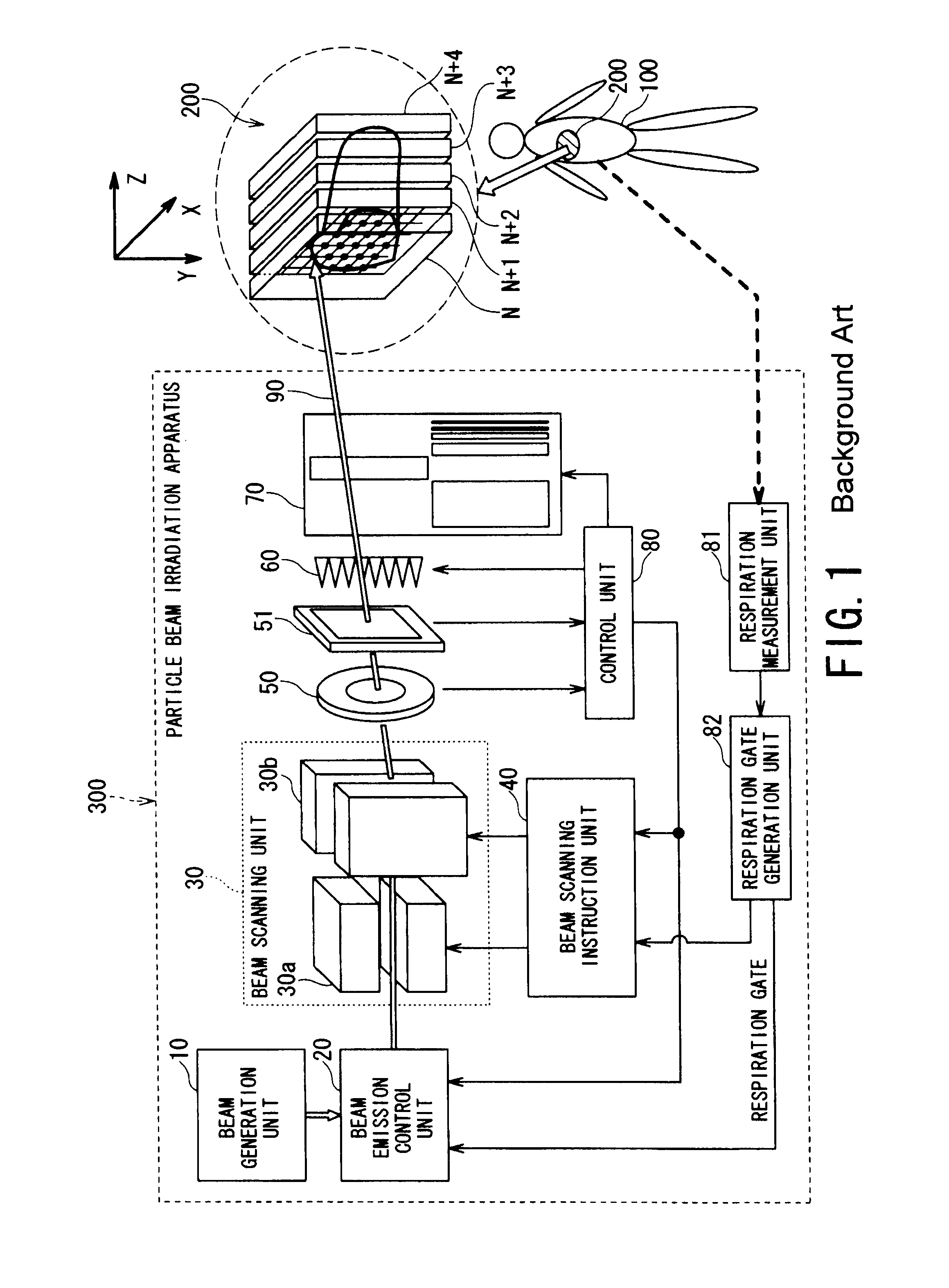
[0072]The particle beam irradiation apparatus 1 according to this embodiment shown in FIG. 7 is different from a conventional particle beam irradiation apparatus 300 (see FIG. 1) in including a pulse generation unit 83.

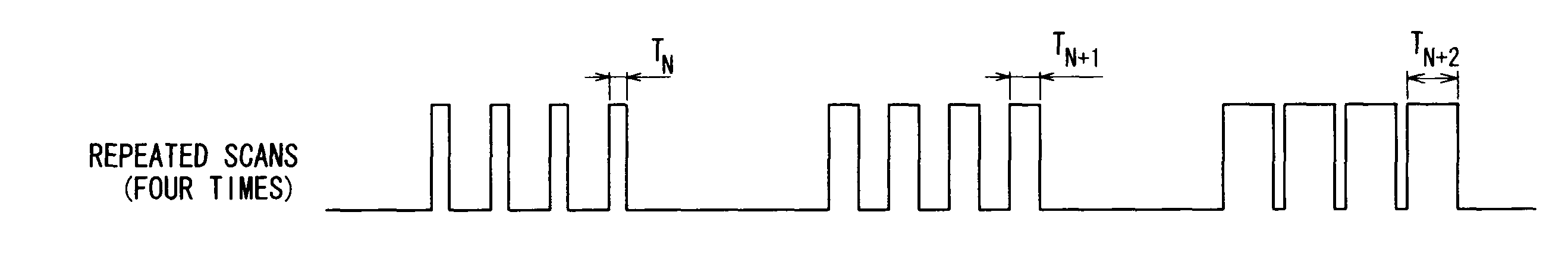
[0073]The pulse generation unit 83 generates a predetermined number of (the number of repeated scans of the same slice) scanning start pulses at substantially equally spaced time intervals in a respiration gate. The scanning start pulse is a timing pulse for determining start timing of each of the repeated scans....

second embodiment

[0106]In the embodiment described above, a scanning direction in the slice is one direction as shown in FIG. 3.

[0107]In a second embodiment, as shown in FIG. 12, a scanning method is used of following a path pattern on a slice in a forward direction (forward path) and then following the same path pattern in a reverse direction (backward path). A hardware configuration is the same as in the first embodiment shown in FIG. 7.

[0108]FIGS. 13A to 13H are timing charts showing operation of a particle beam irradiation apparatus 1 according to the second embodiment.

[0109]First, a scanning start pulse (for forward path) like the scanning start pulse (B) in the first embodiment is generated. This pulse train is for the forward path. This timing is used to start a slice scan of a first forward path.

[0110]In the example shown in FIGS. 13A to 13H, a slice scanning time of the forward path is set to about twice an interval Gw / m or less between the scanning start pulses (for forward path).

[0111]Whe...


PUM


Abstract

A particle beam irradiation apparatus includes: a beam generation unit that generates a particle beam; a beam emission control unit that controls emission of the particle beam; a beam scanning instruction unit that sequentially two-dimensionally instructs a position of the particle beam so that the particle beam is scanned across the entire slice; a beam scanning unit that two-dimensionally scans the particle beam; a respiration gate generation unit that generates a respiration gate synchronized with a respiration cycle of the patient; and a pulse generation unit that generates a predetermined number of scanning start pulses at substantially equally spaced time intervals in the respiration gate. The beam scanning instruction unit instructs to scan the entire slice by pattern irradiation based on a set dose from each of the scanning start pulses so that a scan of the same slice is repeated the predetermined number of times.

Description

TECHNICAL FIELD[0001]The present invention relates to a particle beam irradiation apparatus and a particle beam irradiation method, and more particularly to a particle beam irradiation apparatus and a particle beam irradiation method for irradiating an affected region of the body with a heavy particle beam such as a carbon beam, or a proton beam for cancer therapy.BACKGROUND ART [0002]Cancer is now the leading cause of death in Japan, and more than 300 thousand people die of cancer every year. Under such circumstances, a particle beam therapy method using a heavy particle beam such as a carbon beam, a proton beam has been attracting attention because of its superior features such as a high therapy effect, fewer side effects, or less physical burden. With this therapy method, a particle beam emitted from an accelerator is applied to cancer cells to kill the cancer cells with a little influence on normal tissues.[0003]A currently used particle beam irradiation method in this therapy m...

Claims


Application Information

Patent Timeline
Patent Type & Authority Patents(United States)
IPC IPC(8): A61N5/10
CPCA61N5/1043A61N5/1049A61N5/1044A61N2005/1095A61N5/1064A61N2005/1087
Inventor ISEKI, YASUSHIHANAWA, KATSUSHI
Owner KK TOSHIBA
Why Eureka
Try Eureka