
Low-speed rotary control method and system for cranes

A control method and control system technology, applied in the field of cranes, can solve problems such as inconvenient operation, high low-speed slewing speed, and low-speed slewing too fast

Active Publication Date: 2012-09-19
XUZHOU HEAVY MASCH CO LTD
View PDF5 Cites 6 Cited by
  • Summary
  • Abstract
  • Description
  • Claims
  • Application Information

AI Technical Summary

Problems solved by technology

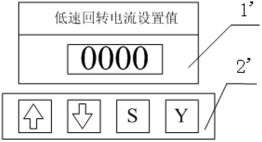
[0007] With the above technical solution, it is necessary to artificially set the low-speed slewing current, which has the following problems: since the buttons and displays for setting the current value are usually set in the control room, if the low-speed slewing current needs to be set, the staff needs to enter the control room to change it, thus It makes the operation inconvenient, and the accuracy of manually setting the current value is low. If the set current value is large, it will cause the low-speed rotation to be too fast, and it is necessary to constantly correct the rotation speed, which will affect the efficiency of the counterweight.
[0008] In addition, when the power is turned off and restarted, the temperature of the working oil will rise and the viscosity will decrease under the new working condition. The low-speed rotation current after manual setting will be relatively large, which will cause the low-speed rotation to be too large. In order to prevent the low-speed rotation from being too large, Manual setting is required to restore the low-speed slewing current to the factory current, which is inconvenient to operate

Method used


Image

  • Low-speed rotary control method and system for cranes
  • Low-speed rotary control method and system for cranes
  • Low-speed rotary control method and system for cranes

Examples


Embodiment Construction

[0039] In order to enable those skilled in the art to better understand the technical solutions of the present invention, the present invention will be further described in detail below in conjunction with the accompanying drawings and specific embodiments.

[0040] Please refer to Figure 4 , Figure 4 It is a flow chart of a specific embodiment of the crane low-speed slewing control method provided by the present invention.

[0041] The low-speed slewing control method of the crane provided by the present invention is used to control the low-speed slewing action of the crane, and the low-speed slewing control method of the crane includes the following steps.

[0042] Step S11, start the rotary valve with preset low-speed rotary current. The operator can energize the control terminal of the rotary valve by pulling the low-speed rotary knob switch arranged at the rear of the vehicle body, and the current energized at the control terminal of the rotary valve is the low-speed ...


PUM


Abstract

The invention relates to the technical field of cranes and discloses a low-speed rotary control method for cranes. The method comprises the following steps: step 11) starting-up a rotary valve by pre-set low-speed rotary current; step 12) detecting a rotary angle of a turntable of the crane; step 13) judging whether the value of the detected rotary angle is greater than a threshold value, if the value of a detected rotary angle is not greater than the threshold value, turning to step 14); step 14) accumulating the low-speed rotary current, and gradually returning back to step 12). The low-speed rotary control method for the cranes can accurately set the needed low-speed rotary current with high efficiency while the low-speed rotary operation is needed. The invention further discloses a low-speed rotary control system of the cranes.

Description

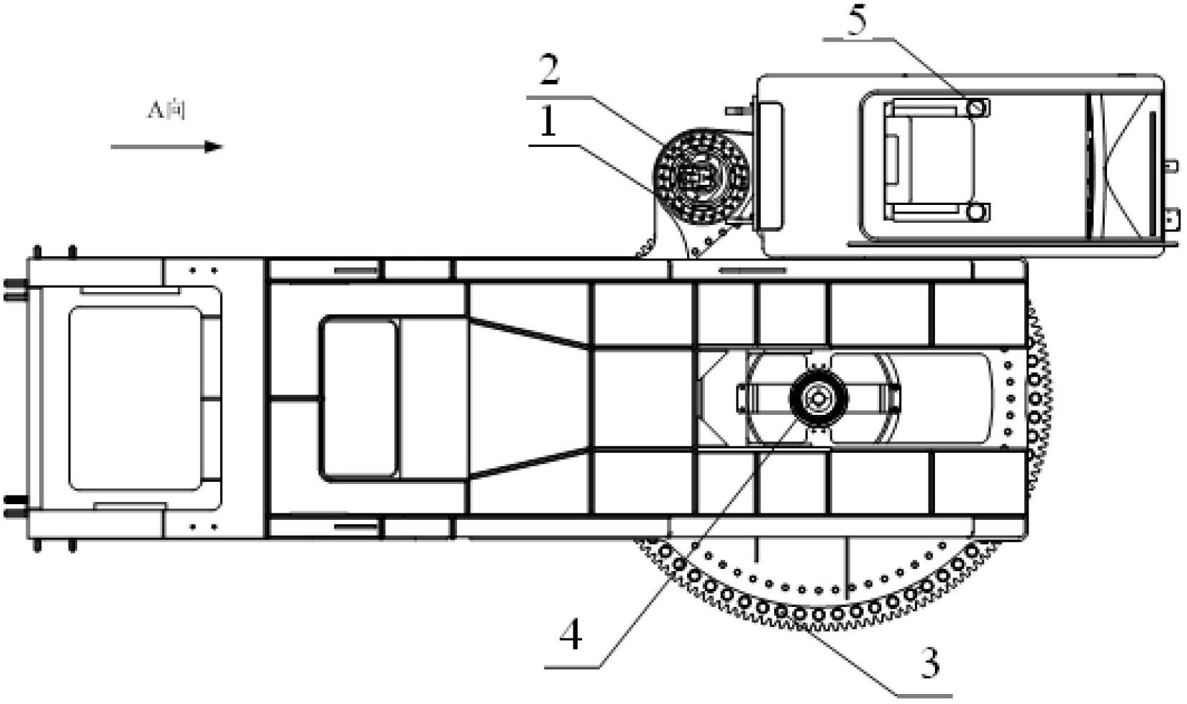
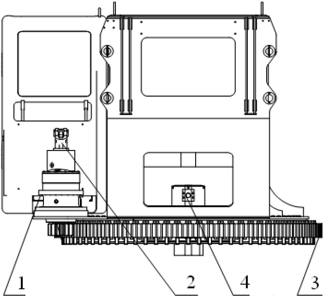
technical field [0001] The invention relates to the technical field of cranes, in particular to a method for controlling low-speed slewing of a crane. The invention also relates to a low-speed slewing control system for the crane. Background technique [0002] The rubber-tyred crane is a kind of full-slewing crane that installs the crane on a special chassis composed of heavy-duty tires and axles. Wheeled cranes usually use a slewing mechanism to realize the slewing operation of the crane in the horizontal plane. [0003] Please see figure 1 , figure 2 , figure 1 It is a structural schematic diagram of a typical crane slewing mechanism; figure 2 for figure 1 Schematic diagram of the structure in direction A. [0004] Such as figure 1 , figure 2 As shown, the slewing mechanism of the rubber-tyred crane usually includes a slewing bearing 3, a slewing reducer 1, a slewing motor 2, a slewing valve, a controller, etc., and the large bottom plate of the turntable of th...

Claims


Application Information

Patent Timeline
Patent Type & Authority Applications(China)
IPC IPC(8): B66C13/20B66C13/16
Inventor 曹立峰李彬张德荣刘威
Owner XUZHOU HEAVY MASCH CO LTD
Learn More