Variable capacitance device

A variable capacitance and variable technology, applied in the direction of capacitors that change the distance between electrodes, can solve problems such as the increase of variable capacitors, and achieve the effect of improving setting accuracy and improving capacitance accuracy.

Active Publication Date: 2012-10-10
MURATA MFG CO LTD
View PDF8 Cites 7 Cited by
  • Summary
  • Abstract
  • Description
  • Claims
  • Application Information

AI Technical Summary

Problems solved by technology

On the other hand, the continuous variable capacitance type is conducive to miniaturization and cost reduction, and there is the following problem: the processing deviation of the spring structure and the like directly become the deviation of the capacitance characteristic of the variable capacitor with respect to the driving voltage, and the current MEMS processing accuracy makes this It is very difficult to get the deviation small enough
In addition, the electrostatic attraction is generated not only by the driving capacitance but also by the signal voltage applied to the variable capacitor, and the electrostatic attraction of the variable capacitor brings the movable plate closer to the substrate. The phenomenon of fixed increase (self-excitation), which is also problematic

Method used


Image

  • Variable capacitance device
  • Variable capacitance device
  • Variable capacitance device

Examples


no. 1 Embodiment approach 》

[0033] A configuration example of the variable capacitance device according to the first embodiment of the present invention will be described.

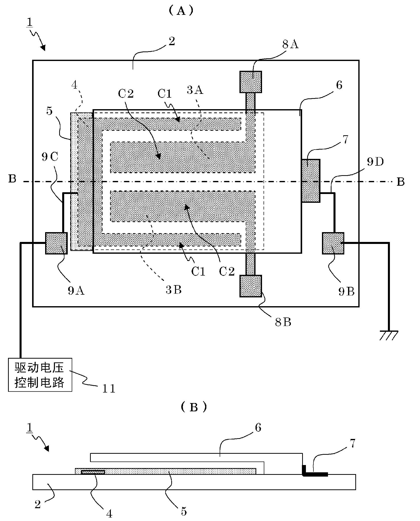
[0034] figure 2 (A) is a plan view of the variable capacitance device 1 . figure 2 (B) is a side sectional view of the variable capacitance device 1 .

[0035]The variable capacitance device 1 includes: a substrate 2, lower driving electrodes 3A, 3B, 4, a dielectric film 5, a beam portion 6, pad electrodes 7, 8A, 8B, 9A, 9B, resistance patterns 9C, 9D, and a driving voltage control circuit 11. The substrate 2 is composed of a rectangular glass substrate. The beam portion 6 has a rectangular flat plate shape in plan view and an L-shape in side view, and serves as a support portion that joins the end portion on the right side in the figure to the base plate 2 , and is a cantilever beam that supports the main part in a state separated from the base plate 2 Structure (spring structure) of the movable structure. The beam portion 6 ...

no. 2 Embodiment approach 》

[0045] Next, a configuration example of the variable capacitance device according to the second embodiment of the present invention will be described. In addition, the variable capacitance device of this embodiment has the same structure as that of the first embodiment, and only the circuit configuration of the driving voltage control circuit is different.

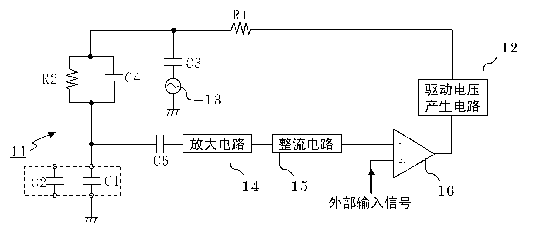
[0046] Figure 4 It is a diagram illustrating the circuit configuration of the driving voltage control circuit 21 of the variable capacitance device according to the present embodiment. In addition, the same code|symbol is attached|subjected to the circuit structure similar to 1st Embodiment.

[0047] The driving voltage control circuit 21 includes a driving voltage generating circuit 22 , an AC signal source 13 for capacitance detection, an AC component active amplifier circuit 24 , a switched capacitor detection circuit 25 , and a comparator 16 . The drive voltage generation circuit 22 includes a switched capacitor LPF...

no. 3 Embodiment approach 》

[0053] Next, a configuration example of the variable capacitance device according to the third embodiment of the present invention will be described. In addition, the circuit configuration of the driving voltage control circuit of the present embodiment is the same as that of the first embodiment, and only the configurations of the driving capacitor unit and the variable capacitor unit are different. In addition, the same code|symbol is attached|subjected to the structure similar to the said structure, and description is abbreviate|omitted.

[0054] Figure 5 (A) is a plan view of the variable capacitance device 31 . Figure 5 (B) is a side sectional view of the variable capacitance device 31 . Figure 5 (C) is a front sectional view of the variable capacitance device 31 .

[0055] The variable capacitance device 1 includes: a substrate 2, lower driving electrodes 3A, 3B, 4, upper driving electrodes 33, 34A, 34B, a dielectric film 5, a beam portion 36, pad electrodes 7, 8A,...


PUM


Abstract

Disclosed is a variable capacitance device (1) which is provided with a substrate (2), a beam section (6), a drive capacitance (C1), a variable capacitance (C2), and a drive voltage control circuit (11). The beam section (6) has the cantilever structure and is connected to the substrate (2). The drive capacitance (C1) is configured to face on the beam section (6) and the substrate (2), and displaces the beam section (6) corresponding to an electrostatic attractive force generated when a DC voltage is applied. The variable capacitance is configured to face on the beam section (6) and the substrate (2), and changes the capacitance corresponding to the displacement of the beam section (6). The drive voltage control circuit (11) detects a detection voltage that changes corresponding to the drive capacitance (C1), and controls the DC voltage to be applied to the drive capacitance (C1) so that the detection voltage is close to a desired value.

Description

technical field [0001] The present invention relates to a variable capacitance device that uses MEMS driven by electrostatic force to realize a variable capacitor. Background technique [0002] In the prior art, a varactor diode is used as a variable capacitor. A varactor diode is a type of semiconductor diode. When a reverse voltage is applied, a depletion layer in which no carriers exist is formed in a PN junction, and it operates as a capacitance with an electrostatic capacity corresponding to the thickness of the depletion layer. When the magnitude of the reverse voltage applied to the varactor is changed, the thickness of the depletion layer changes and the capacitance changes, so that the varactor can be operated as a variable capacitor. Among them, a varactor diode has a small Q as a capacitor and has a large loss, and therefore cannot be used in a circuit requiring a low-loss capacitor, such as a wireless communication circuit, in many cases. Therefore, in circuits...

Claims


Application Information

Patent Timeline
Patent Type & Authority Applications(China)
IPC IPC(8): H01G5/16H01G5/18
CPCH01G5/18
Inventor 柴原辉久
Owner MURATA MFG CO LTD
Why Eureka
Try Eureka