Extension connector for an angle adjustable cymbal stand

Inactive Publication Date: 2005-08-11
HSIEH WU HONG
View PDF5 Cites 4 Cited by
  • Summary
  • Abstract
  • Description
  • Claims
  • Application Information

AI Technical Summary

Benefits of technology

[0008] The primary objective of the present invention is to provide an improved angle adjustable cymbal stand having an extension connector to allow the operator to have sufficient room to cope with the space limit problem.
[0009] Another objective of the present invention is that the extension corrector is simple in assembly and inexpensive in manufacture yet the function provided enables the cymbal stand to enlarge the angle adjusting range.

Problems solved by technology

That is, if a cymbal set is required and each of the cymbals is connected to one another closely, it is almost impossible to have room enough to allow the operator to proceed the angle adjusting process.

Method used


Image

  • Extension connector for an angle adjustable cymbal stand
  • Extension connector for an angle adjustable cymbal stand
  • Extension connector for an angle adjustable cymbal stand

Examples


Embodiment Construction

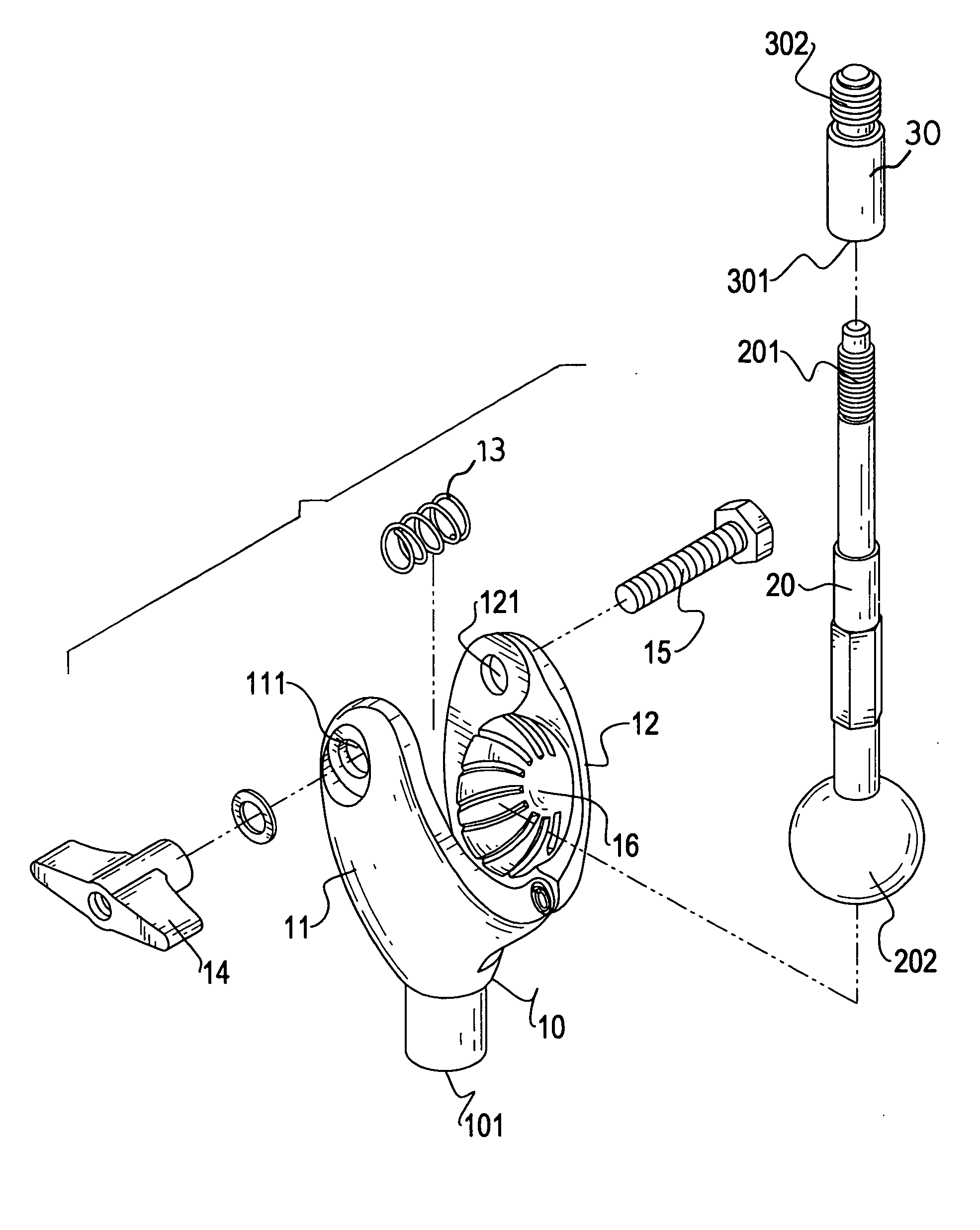
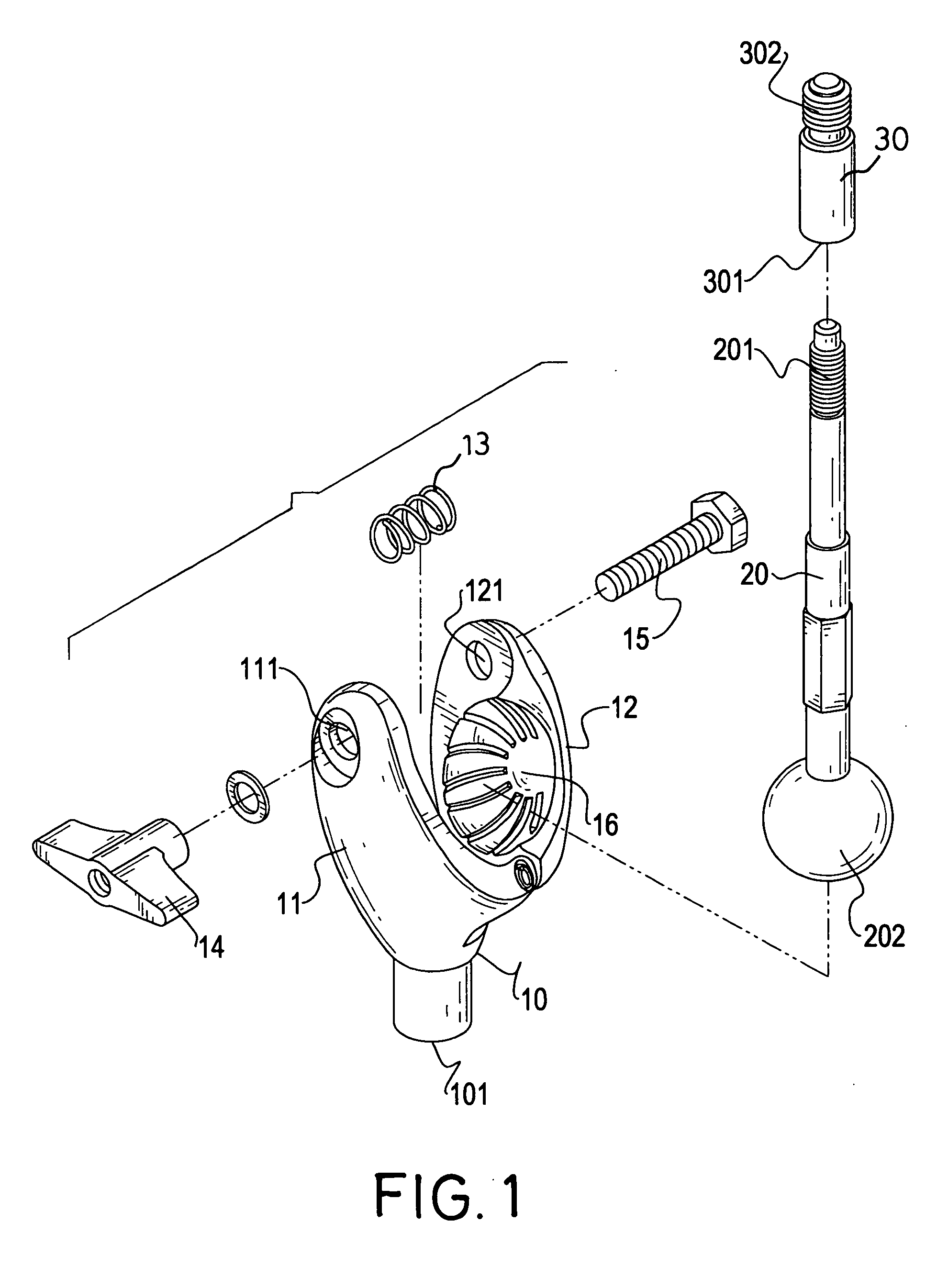
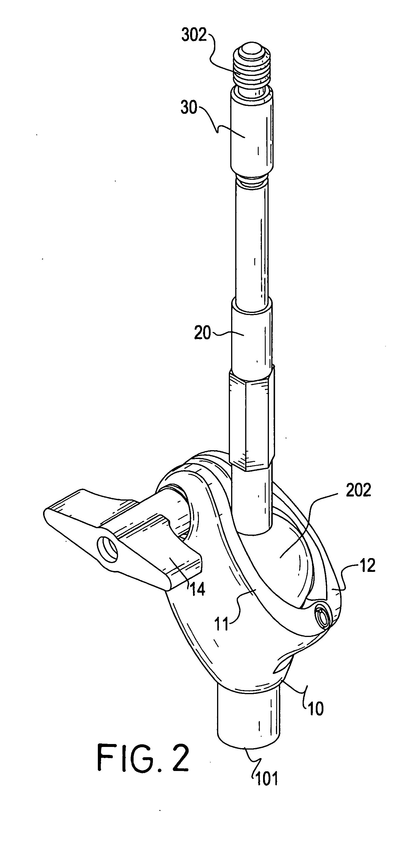
[0016] With reference toFIG. 1, the angle adjustable cymbal stand in accordance with the present invention has a receptacle (10) composed of two halves (11,12) pivotally connected with one another and defining therebetween a space (16), a ball linkage (20) having a first threaded end (201) at one end and a ball (202) at the other end and an extension connector (30) having a first threaded hole (301) at a first end of the extension connector (30) to correspond to the first threaded end (201) of the ball linkage (20) and a second threaded end (302) at a second end of the extension connector (30).

[0017] The receptacle (10) has a second threaded hole (101) defined in a bottom face of the receptacle (10) to correspond to the first threaded end (201) of the ball linkage (20). Each of the two halves (11,12) has a through hole (111,121) defined to align with one another and to allow a threaded bolt (15) to extend therethrough. A spring (13) is received in the space (16) and mounted around ...


PUM


Abstract

An extension connector has a threaded end formed on a first end of the extension connector for connection with a threaded hole of a receptacle and a threaded hole adapted for connection with a threaded end of a ball linkage such that an angle adjustable cymbal stand is able to extend to any position for connection with a cymbal.

Description

BACKGROUND OF THE INVENTION [0001] 1. Field of the Invention [0002] The present invention relates to an extension connector, and more particularly to an extension for an angle adjustable cymbal stand to enable the adjustable cymbal stand to not only extend to a desired length but also adjust to a desired angle. [0003] 2. Description of Related Art [0004] With reference to FIGS. 4 and 5, a conventional angle adjustable cymbal stand is shown to have a seat (50) firmly engaged with a support rod (61) extending from a stand (60) and a rod (52) extending from a ball (51) which is movably received in the seat (50). A knob (53) is provided on a side of the seat (50) to control the movement of the ball (51) inside the seat (50). A cymbal (64) is securely connected to the rod (52) and a nut (63) is provided to engage with a free end of the rod (52) after the rod (52) extends through the cymbal (64). A spacer (62) is sandwiched between the cymbal (64) and the nut (63). [0005] Therefore, when ...

Claims


Application Information

Patent Timeline
IPC IPC(8): F16M11/14G10D13/063G10G5/00
CPCF16M11/14F16M11/2078G10D13/06F16M2200/022F16M11/245G10D13/28G10D13/063
Inventor HSIEH, WU-HONG
Owner HSIEH WU HONG
Why Eureka
Try Eureka