
Charge holder apparatus

a technology of charging holder and charging tube, which is applied in the direction of nuclear explosives, nuclear engineering, borehole/well accessories, etc., can solve the problem that standard or universal loading tubes cannot be used, and achieve the effect of increasing charges

Active Publication Date: 2005-08-11
SCHLUMBERGER TECH CORP
View PDF5 Cites 27 Cited by
  • Summary
  • Abstract
  • Description
  • Claims
  • Application Information

AI Technical Summary

Benefits of technology

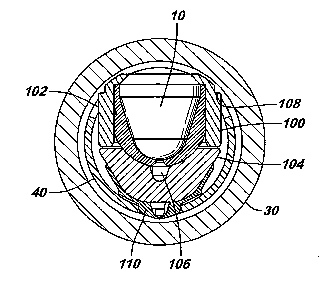
The present invention provides an adapter that allows for the mounting of different sizes of shaped charges into a standard or universal loading tube. The adapter includes a charge holder or a charge jacket with support ribs and a latching mechanism for securely fitting the small shaped charge into the larger gun. This allows for easy customization and flexibility in the use of shaped charges in various applications.

Problems solved by technology

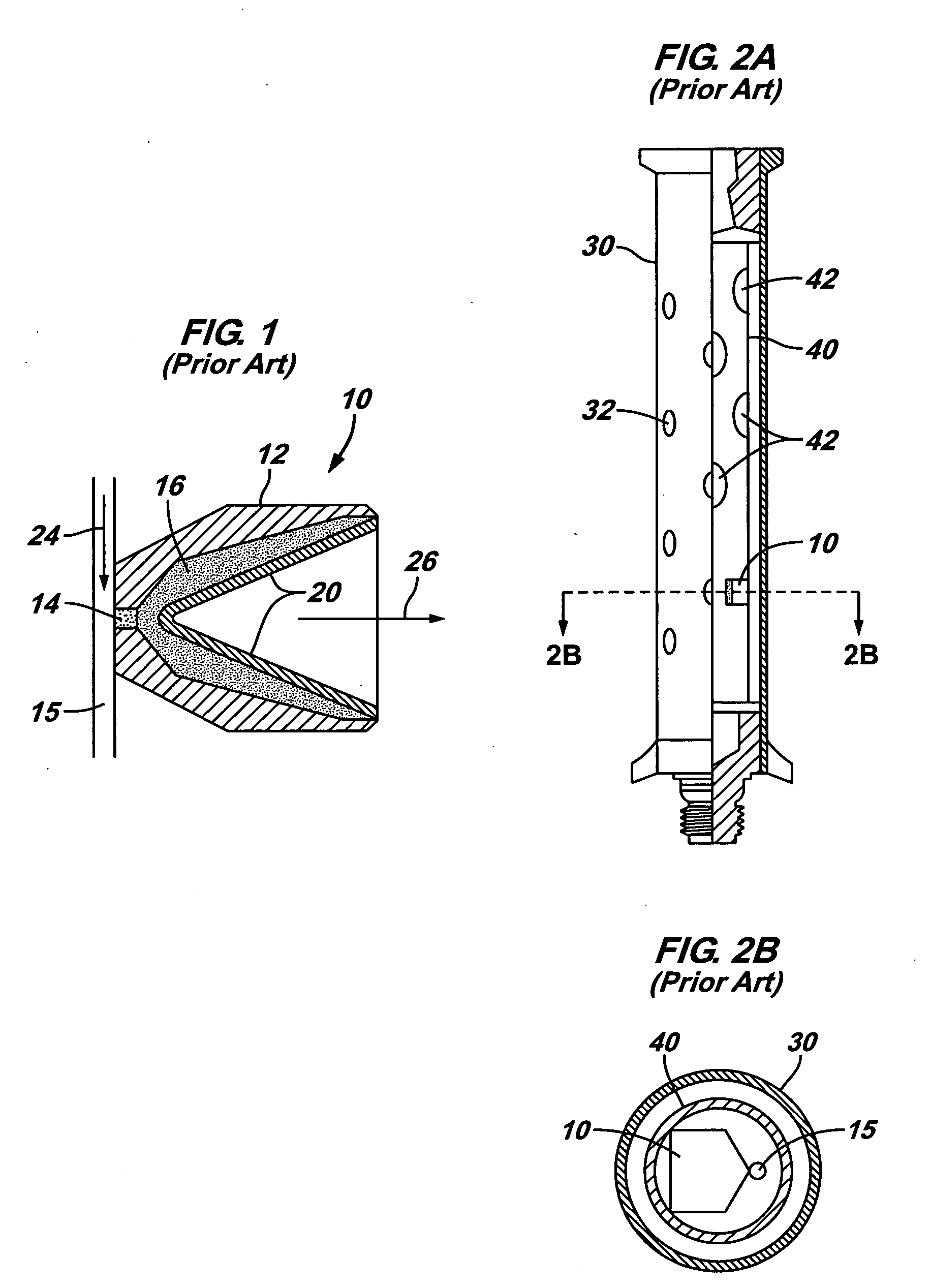
The difficulty with conventional hollow carrier guns is that conventional loading tubes are designed to receive only one particular size of shaped charge.
Accordingly, if a perforation plan calls for using shaped charges of non-standard sizes (e.g., small shaped charges in a large gun), then a standard or universal loading tube cannot be used and a specialized loading tube must be fabricated.

Method used


Image

  • Charge holder apparatus
  • Charge holder apparatus
  • Charge holder apparatus

Examples


Embodiment Construction

[0023] In the following description, numerous details are set forth to provide an understanding of the present invention. However, it will be understood by those skilled in the art that the present invention may be practiced without these details and that numerous variations or modifications from the described embodiments may be possible.

[0024] In the specification and appended claims: the terms “connect”, “connection”, “connected”, “in connection with”, and “connecting” are used to mean “in direct connection with” or “in connection with via another element” and the term “set” is used to mean “one element” or “more than one element”. As used herein, the terms “up” and “down”, “upper” and “lower”, “upwardly” and downwardly”, “upstream” and “downstream”“above” and “below” and other like terms indicating relative positions above or below a given point or element are used in this description to more clearly described some embodiments of the invention. However, when applied to equipment...


PUM


Abstract

An adapter is provided for holding and mounting a shaped charge having a non-standard size into a standard loading tube of a hollow carrier gun. The adapter may include a housing assembly having an interior bore to hold a relatively small shaped charge and an exterior surface sized for mounting in a standard loading tube via a standard jacket. Alternatively, the adapter may include an improved jacket having interior ribs for supporting a relatively small shaped charge and an exterior surface for mounting the shaped charge in a standard loading tube of a relatively large gun.

Description

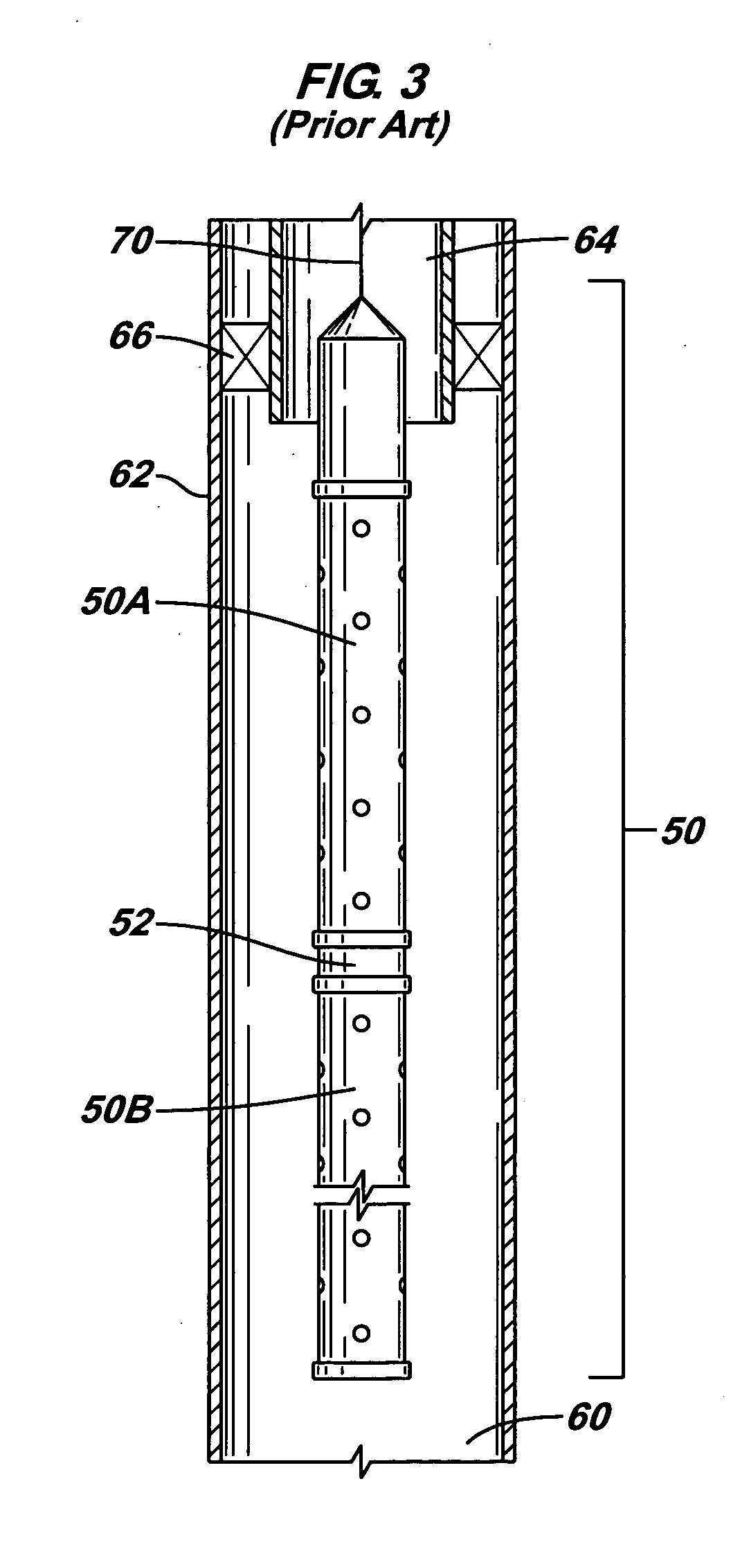
BACKGROUND OF INVENTION [0001] The present invention relates generally to perforating tools used in downhole applications, and more particularly to a holding device for supporting charges in a perforating gun for use in a wellbore. [0002] After a well has been drilled and casing has been cemented in the well, one or more sections of the casing, which are adjacent to formation zones, may be perforated to allow fluid from the formation zones to flow into the well for production to the surface or to allow injection fluids to be applied into the formation zones. A perforating gun string may be lowered into the well to a desired depth and the guns fired to create openings in the casing and to extend perforations into the surrounding formation. Production fluids in the perforated formation can then flow through the perforations and the casing openings into the wellbore. [0003] Typically, perforating guns (which include gun carriers and shaped charges mounted on or in the gun carriers) are...

Claims


Application Information

Patent Timeline
Patent Type & Authority Applications(United States)
IPC IPC(8): E21BE21B43/11E21B43/116E21B43/117F42D1/22
CPCE21B43/117
Inventor LI, HAOMINGDUHON, MARK C.RATANASIRIGULCHA, WANCHAIHENDERSON, STEVEN W.
Owner SCHLUMBERGER TECH CORP
Learn More