Device and method for lubricating bearings

a technology for bearings and lubricating devices, applied in the direction of bearings, engine lubrication, ball bearings, etc., can solve the problems of zerk grease fittings that typically take more than 10,000 psi of pressure, no of these basic design and grease methods guarantee that grease will enter the bearing, and partially plugged, so as to achieve accurate and reliable results, and minimal amount of greas

Inactive Publication Date: 2005-08-11
LATHAM GARY J
View PDF4 Cites 10 Cited by
  • Summary
  • Abstract
  • Description
  • Claims
  • Application Information

AI Technical Summary

Benefits of technology

[0019] An additional object of the present invention is to introduce an innovative, state of the art lubrication technique which will render current methods of greasing ineffective, making existing industrial lubrication charts obsolete, and thus creating a new in...

Problems solved by technology

Neither of these basic design and grease methods guarantee that the grease will enter the bearing, because the grease can easily migrate out through the seals or drain plugs.
Old grease can also be pushed into the bearings, ...

Method used


Image

  • Device and method for lubricating bearings
  • Device and method for lubricating bearings

Examples


Embodiment Construction

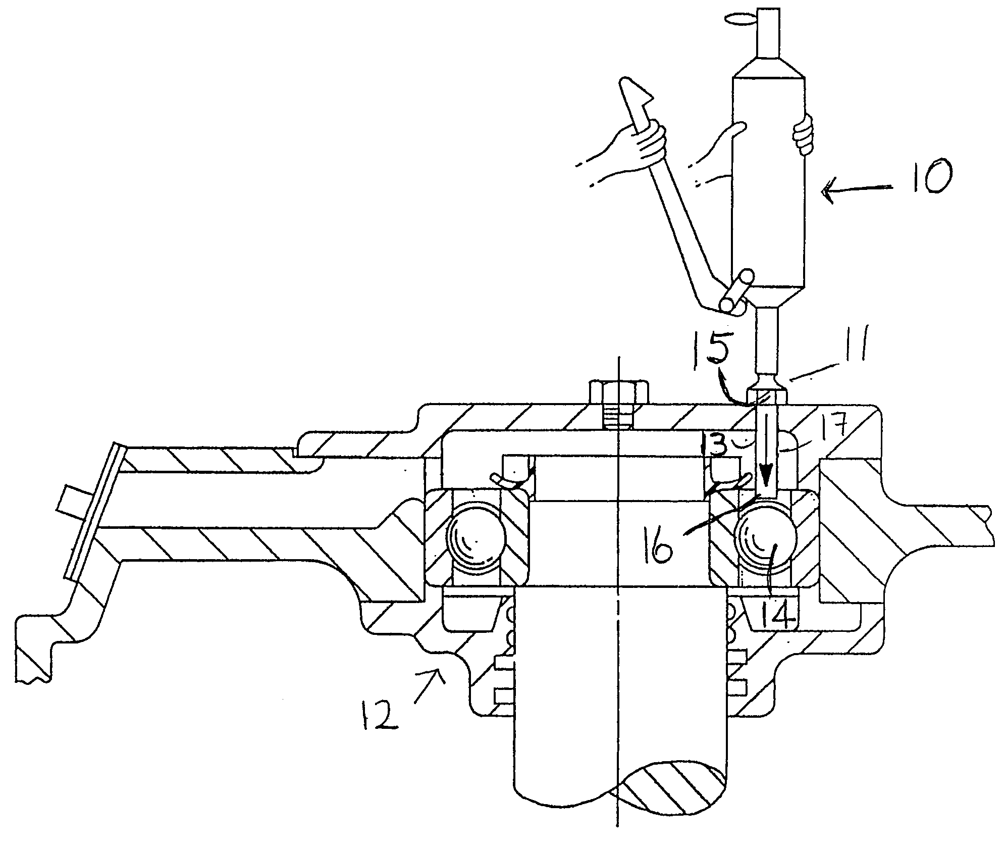
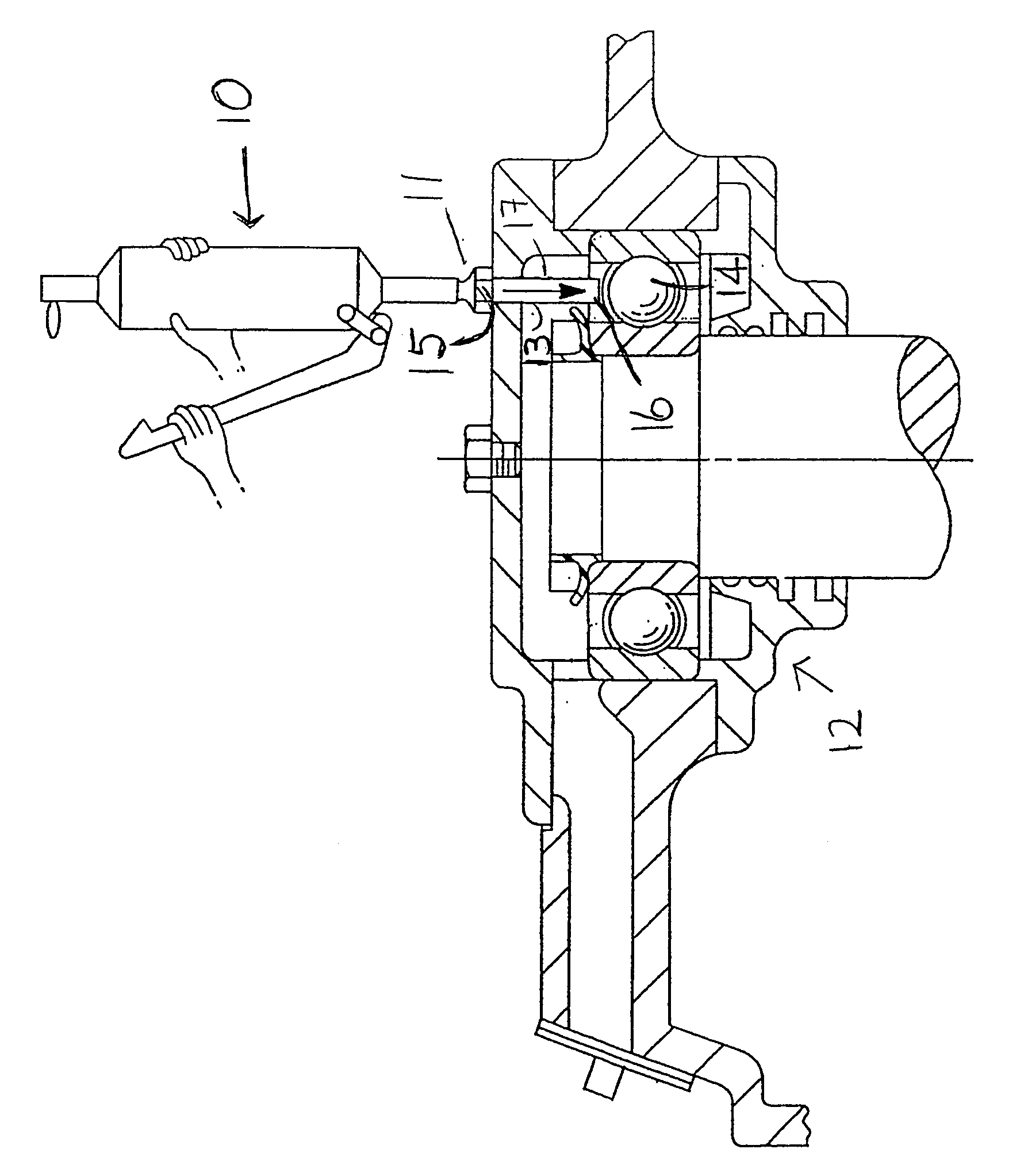
[0023] With reference to the accompanying drawing, there is shown a conventional grease gun 10 being applied to a zerk grease fitting 11 of a bearing assembly 12.

[0024] The main component of the present invention comprises a tube 13 which is disposed between the zerk grease fitting 11 and the bearing rolling elements 14 to be lubricated. In accordance with the present invention, the tube 13 is affixed to the interior portion of the zerk grease fitting 11, and extends so that the interior opening or end 16 of the tube 13 is in close proximity to the bearing rolling elements 14 to be lubricated.

[0025] The grease moves through the tube 13 in the direction of the arrow 17.

[0026] Preferably, but not necessarily, the end 16 of the tube 13 will emit grease at approximately 90 degrees to the face of the bearing elements 14.

[0027] The tube 13 may be fabricated from any suitable material. Preferably, but not necessarily, the tube 13 may be fabricated from plastic, and wherein the plastic ...


PUM


Abstract

A lubricating device and method for delivering fresh grease to a rolling element bearing in a first cavity, by by-passing all existing grease in the first cavity and in other cavities surrounding and/or leading to the rolling element bearing, and delivering fresh grease in close proximity to the rolling element bearing. A tube is disposed between the zerk fitting and the bearing to ensure delivery of the fresh new grease to the bearing.

Description

[0001] The present patent application claims priority from and is based on U.S. Provisional Patent Application Ser. No. 60 / 542,214 filed Feb. 5, 2004 the entire contents of which are incorporated herein by reference thereto.[0002] The present invention relates generally to a novel and unique device and method for delivering fresh grease to rolling element bearings. [0003] More particularly, the present invention relates to a novel and unique device and method of delivering fresh grease to rolling element bearings which will guarantee that each shot of grease reaches the bearing. BACKGROUND OF THE INVENTION [0004] Heretofore, there were two basic designs of grease paths in the housings of ball and cylindrical roller bearings. The most common design entails having the grease enter a cavity on the outer side of the bearing. The other basic design is used primarily on motors where grease enters a cavity on the inner side of the bearing. [0005] Neither of these basic design and grease me...

Claims


Application Information

Patent Timeline
IPC IPC(8): F16C33/10F16C33/66F16N3/10F16N5/02
CPCF16N2210/14F16C33/6622F16C19/06F16C35/042
Inventor LATHAM, GARY J.
Owner LATHAM GARY J
Why Eureka
Try Eureka