
Rod maker, method for operating the same and air conveyor system

a technology of air conveyor and rod maker, which is applied in the direction of tobacco, tobacco manufacture, tobacco treatment, etc., can solve the problems of deteriorating efficiency of method and rod maker, changing the rib discharge from the tobacco flow to be sifted with the productive capacity of the rod maker, etc., and achieves the effect of precise air flow, cost-effective, and effective and simple opportunity

Inactive Publication Date: 2005-08-18
HAUNI MASCHINENBAU AG
View PDF1 Cites 2 Cited by
  • Summary
  • Abstract
  • Description
  • Claims
  • Application Information

AI Technical Summary

Benefits of technology

[0012] By keeping the sum of the air throughput of the third and fourth air flow to an essentially constant value, irrespective of the productive capacity of the rod maker, it is possible to influence the air pressure in the chamber such that a uniform sifting of the tobacco flow is rendered possible. The lower the productive capacity of the rod maker, the faster the suction belt of the suction rod conveyor, which can also be a suction belt conveyor within the scope of the invention, seals up by the application of tobacco so that less air in the form of the third air flow is carried away out of the chamber via the suction rod conveyor. The air throughput conveyed out of the chamber in the form of the fourth air flow should then be increased accordingly so that the air speed at the sifter, comprising a pre-sifter and optionally a post-sifter, does not change too much and preferably remains constant so that the rib discharge from the tobacco flow also remains constant. This effect occurs essentially because the pressure in the chamber remains essentially constant so that the air speed at the sifter does not have to be changed. The sum of the air throughputs of the third and fourth air flow is kept constant automatically or when the rod maker is running.
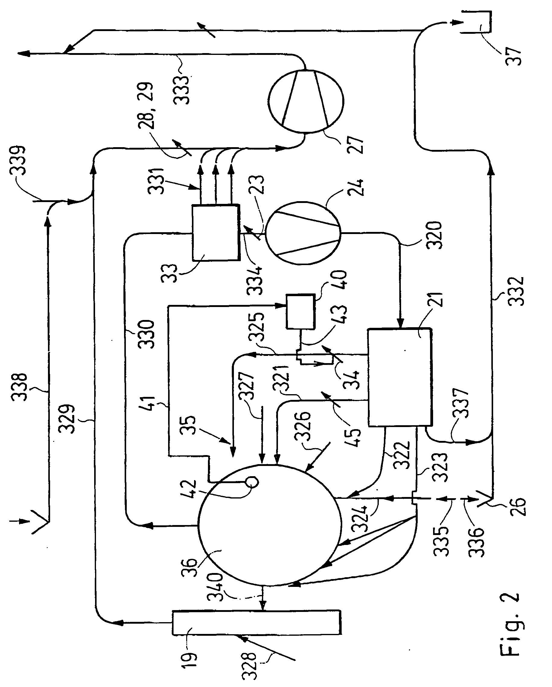
[0024] An air distributor is preferably arranged downstream of the circulation fan and upstream of the chamber. A particularly effective air guidance is rendered possible in the air conveyor system if by releasing air upstream of the chamber it is made possible to keep constant the air throughput that can be conveyed out of the chamber. It is expedient to provide a throttle flap in a pipe discharging air into the surroundings. Preferably, an essentially constant pressure can be established in the chamber. To this end, e.g., a pressure sensor can be used in the chamber. The aspect can be attained very effectively if a control or regulating device is provided to control or regulate the air throughput released into the surroundings. The control or regulation preferably occurs continuously or progressively, and with the latter alternative two positions or three positions of the throttle flap are preferably provided or two or three predetermined air throughputs can be predetermined.

Problems solved by technology

However, with such a method, such a rod maker and such an air conveyor system, the effect occurs that the rib discharge from the tobacco flow to be sifted changes with the productive capacity of the rod maker.
Thus, e.g., when the productive capacity is cut back, more tobacco is sifted out, which leads to a deterioration of the efficiency of the method and of the rod maker.

Method used


Image

  • Rod maker, method for operating the same and air conveyor system
  • Rod maker, method for operating the same and air conveyor system
  • Rod maker, method for operating the same and air conveyor system

Examples


Embodiment Construction

[0037] The particulars shown herein are by way of example and for purposes of illustrative discussion of the embodiments of the present invention only and are presented in the cause of providing what is believed to be the most useful and readily understood description of the principles and conceptual aspects of the present invention. In this regard, no attempt is made to show structural details of the present invention in more detail than is necessary for the fundamental understanding of the present invention, the description taken with the drawings making apparent to those skilled in the art how the several forms of the present invention may be embodied in practice.

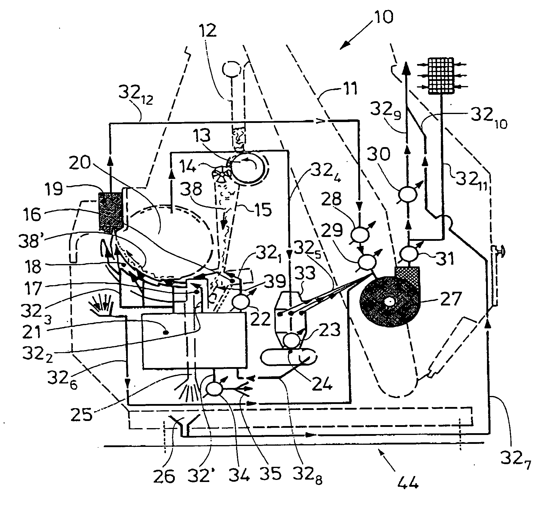
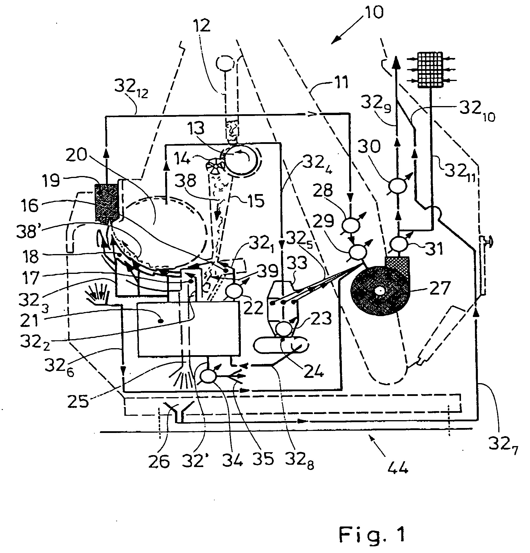
[0038]FIG. 1 shows diagrammatically a rod maker 10 according to the invention. In the rod maker 10 several elements represented by a dotted line will be explained below.

[0039] Tobacco is conveyed from a tobacco supply by a steep wall conveyor 11 to a retaining duct 12. Tobacco is removed from the retaining duct 12 by a...


PUM


Abstract

A method of operating a rod maker for tobacco processing that includes sifting a tobacco flow in a chamber of the rod maker with a first air flow to separate tobacco ribs from the tobacco flow and conveying the sifted tobacco flow in the chamber by at least one of the first air flow and a second air flow. Moreover, the method includes conveying air out of the chamber via a third air flow and a fourth air flow, where a sum of an air throughput of the third air flow and the fourth air flow is substantially constant, irrespective of a productive capacity of the rod maker. The instant abstract is neither intended to define the invention disclosed in this specification nor intended to limit the scope of the invention in any way.

Description

CROSS-REFERENCE TO RELATED APPLICATIONS [0001] The present application claims priority under 35 U.S.C. §119 of German Patent Application No. 10 2004 007 841.6, filed on Feb. 17, 2004, the disclosure of which is expressly incorporated by reference herein in its entirety. BACKGROUND OF THE INVENTION [0002] 1. Field of the Invention [0003] The invention relates to a method for operating a rod maker (rod-making machine) for tobacco processing, in which a tobacco flow is sifted in a chamber of the rod maker by a first air flow so that tobacco ribs are separated from the tobacco flow, in which the sifted tobacco flow is conveyed in the chamber by the first and / or a second air flow, in which a third and a fourth air flow are provided which convey air out of the chamber. The invention further relates to a rod maker of the tobacco processing industry comprising a tobacco sifter, a suction rod conveyor and a device for conveying tobacco to the suction rod conveyor, in which the device for con...

Claims


Application Information

Patent Timeline
Patent Type & Authority Applications(United States)
IPC IPC(8): A24C5/14A24C5/18A24C5/39
CPCA24C5/18A24C5/396A24C5/392A24C5/1871
Inventor HERBURG, ANDREAS
Owner HAUNI MASCHINENBAU AG
Learn More