Combined ablation and exposure system and method

a technology of flexographic printing plate and exposure system, which is applied in the field of combination ablation and exposure system, can solve the problems of flexographic plate loss, unsatisfactory handling, and high cost of flexographic pla

Active Publication Date: 2005-08-25
ESKO GRAPHICS IMAGING +1
View PDF7 Cites 23 Cited by
  • Summary
  • Abstract
  • Description
  • Claims
  • Application Information

AI Technical Summary

Problems solved by technology

In the conventional two step process, great care must be taken in handling the plate after it has been ablated and before it has been exposed, as the carbon on the plate can be easily scratched or otherwise blemished in a way that renders useless the image represented on the plate.
Flexographic plates are expensive, and losing plates due to corruption resulting from handling is therefore quite undesirable.
In addition, flexographic plates can also be quite large in some applications, requiring a very large flatbed exposure device which can also be quite expensive.
Repeated pulses of light are not as effective in exposing the plate as continuous exposure, making this solution less than ideal.

Method used


Image

  • Combined ablation and exposure system and method
  • Combined ablation and exposure system and method
  • Combined ablation and exposure system and method

Examples


Embodiment Construction

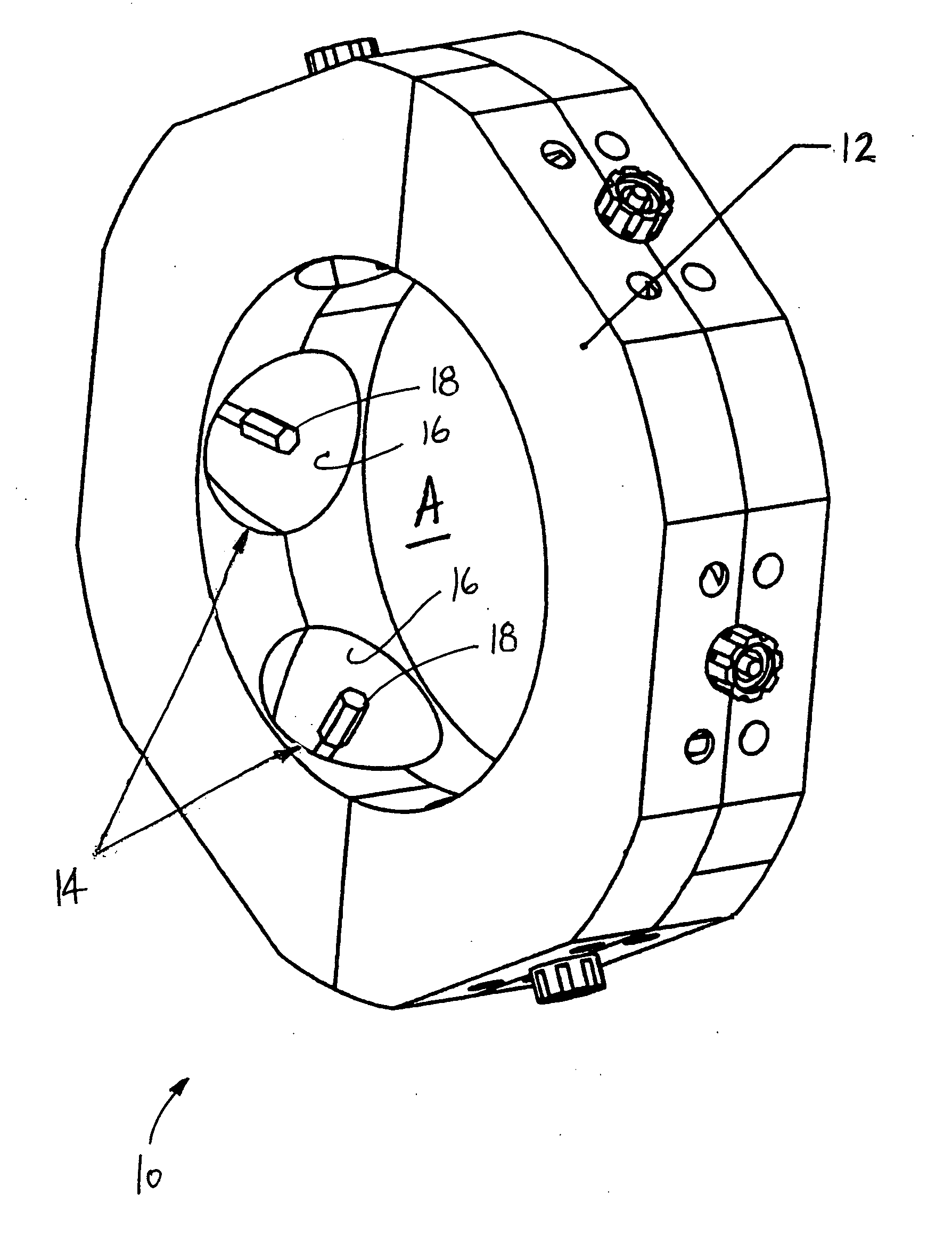
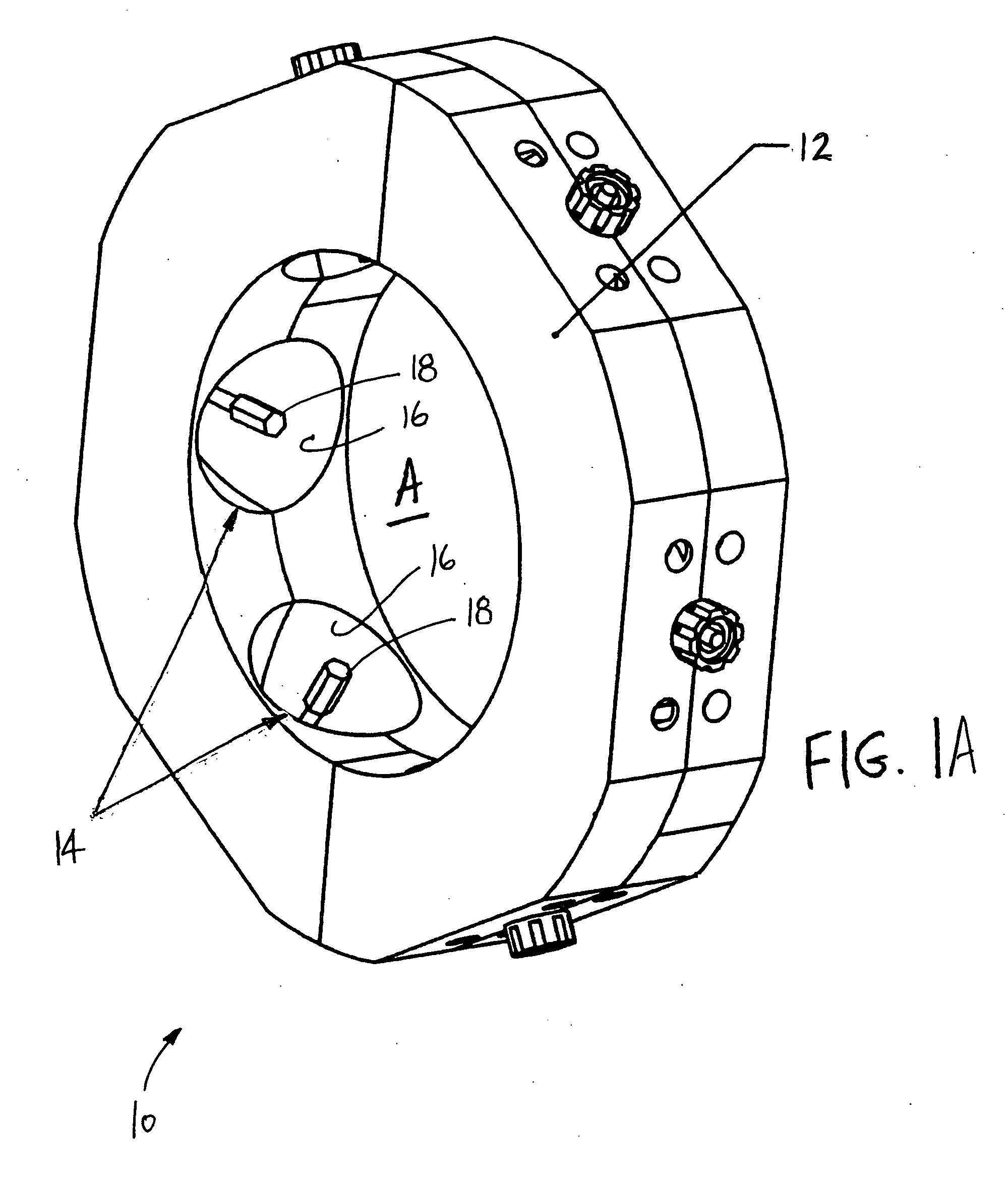
[0013] The present invention provides an exposure system that surrounds a photopolymer such as a flexographic plate in a rotating cylinder ablation system, the exposure system linearly following the ablation source and operating to expose the ablated (masked) plate with high intensity illumination from all sides so as to continuously expose all points on the plate. The flexographic printing plate may be mounted to a rotating cylinder, or may itself be a cylindrical sleeve type of plate.

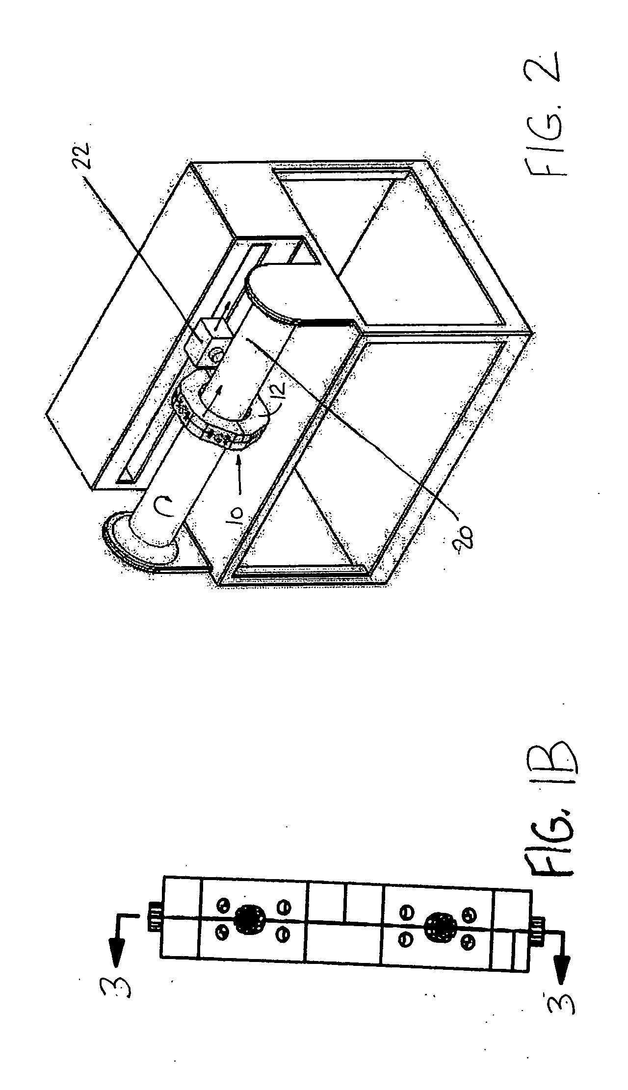
[0014]FIG. 1A is a perspective diagram, and FIG. 1B is a side view, of exposure system 10 of the present invention. Body 12, having a toroidal geometry and being made of a material such as aluminum for example, is provided to surround a rotating cylinder (not shown in FIG. 1, but which fits inside aperture A) on which a flexographic plate is mounted. A plurality of high intensity light sources 14 are provided in body 12, each of which is operable to direct high intensity light inward toward the flexo...


PUM

PropertyMeasurementUnit
lengthaaaaaaaaaa
illumination angleaaaaaaaaaa
rotationaaaaaaaaaa

Abstract

An exposure system is provided that surrounds a photopolymer on a rotating cylinder ablation system. The exposure system linearly follows the ablation source and operates to expose the ablated (masked) plate with high intensity illumination from all sides so as to continuously expose all points on the photopolymer.

Description

CROSS-REFERENCE TO RELATED APPLICATION(S) [0001] This application claims priority from provisional application No. 60 / 547,652 filed Feb. 25, 2004, for “Combined Ablation and Exposure System and Method” by Frank A. Hull and Benn Horrisberger.BACKGROUND OF THE INVENTION [0002] The present invention relates to ablation and exposure of flexographic printing plates, and more particularly to a system and method of continuously exposing a flexographic plate on a rotating cylinder that is also used to ablate the plate. [0003] Digital flexographic printing plates are conventionally exposed in two steps. The first step is to ablate the plate in a pattern that defines a mask on the plate. The mask represents the graphical image that the plate is used to print. This step is typically performed by placing the plate on a rotating cylinder and ablating the plate with a linearly movable imaging source controlled to ablate the desired image into the overcoat of the plate. The second step of the proc...

Claims


Application Information

Patent Timeline
Patent Type & Authority Applications(United States)
IPC IPC(8): B41C1/05B41N1/14G03F7/00
CPCG03F7/24
Inventor HULL, FRANK A.HORRISBERGER, BENN
Owner ESKO GRAPHICS IMAGING
Why Eureka
Try Eureka