Remote actuator for ball injector

Inactive Publication Date: 2005-08-25
S P M FLOW CONTROL
View PDF8 Cites 58 Cited by
  • Summary
  • Abstract
  • Description
  • Claims
  • Application Information

AI Technical Summary

Problems solved by technology

Sometimes several hundred balls are used, so at times it is very difficult to keep track of the number of balls that have been inserted.
However, prior versions could not be

Method used


Image

  • Remote actuator for ball injector
  • Remote actuator for ball injector
  • Remote actuator for ball injector

Examples


Embodiment Construction

[0016] Although the following detailed description contains many specific details for purposes of illustration, anyone of ordinary skill in the art will appreciate that many variations and alterations to the following details are within the scope of the invention. Accordingly, the exemplary embodiment of the invention described below is set forth without any loss of generality to, and without imposing limitations thereon, the claimed invention.

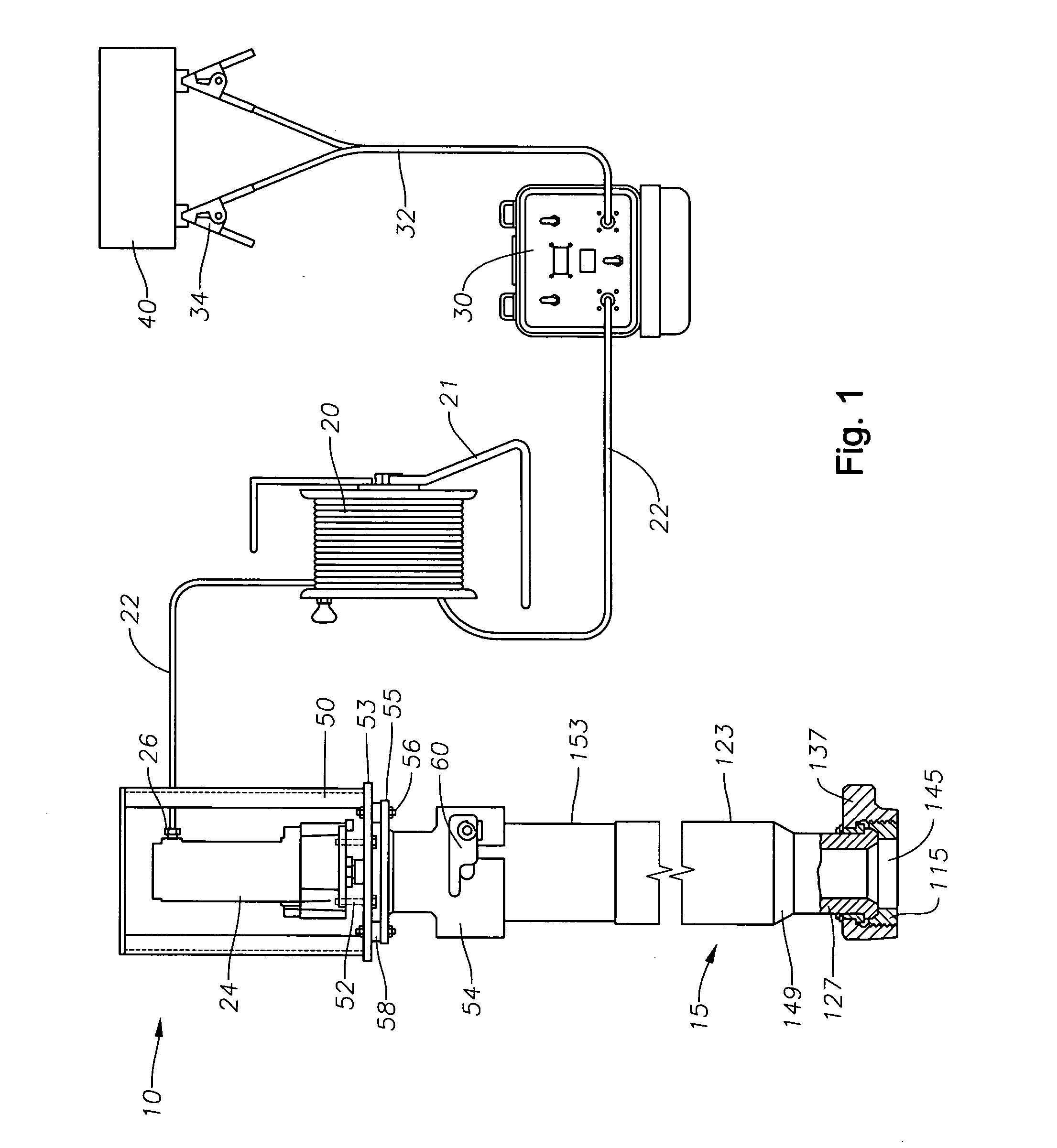
[0017]FIG. 1 shows a schematic of all component parts relating to the operation of the remote actuator 10 and the ball injector 15. A cable reel 20, which is supported by a reel stand 21, comprises a roll of control cable 22. To assemble the remote actuator system 10 for operation, the control cable 22 is unrolled from one end of the cable reel 20 and connected to an electric motor 24 by fastener 26. Then the control cable 22 is unrolled from the other end of the cable reel 20 and connected to the output port of the control panel 30. The leng...


PUM


Abstract

An electrical motor rotatably drives a motor shaft, and a helical rib radially extends from the shaft. The helical rib supports a number of balls, and forms a channel to accommodate the balls. The balls are dropped from the helical rib when the balls reach the bottom of the helical rib. Several targets are affixed to the shaft. A sensor is located adjacent to and apart from the shaft, and is positioned in close proximity to the targets. The sensor senses each target as each target rotates past the sensor. The number of targets sensed per revolution of the shaft is equal to the number of balls dropped from the helical rib per revolution of the helical rib. A counter in data communication with the sensor displays the number of targets sensed, and thus displays the number or balls dropped from the helical rib.

Description

1. FIELD OF THE INVENTION [0001] This invention relates to a remote actuator for injecting spherical balls into an oil well. More particularly, this invention relates to a target and sensor mechanism that effectively counts the number of balls injected into the well. 2. BACKGROUND OF THE INVENTION [0002] When an oil or gas well is completed, it is common practice to cement the well casing into the well. The casing is then perforated to allow fluid from the producing formations to flow into the well bore. [0003] In order to increase the productivity of oil and gas wells, producing formations are sometimes treated by hydraulic fracing and acidizing. Hydraulic treading fluid is pumped into the well bore and exits through the perforations in the casing into the formation. [0004] If some of the perforations are blocked by sediment, or if part of a formation has a lower permeability, part of the formation may not have been treated by fracing. To insure that this does not happen, perforati...

Claims


Application Information

Patent Timeline
IPC IPC(8): E21B33/05E21B33/068E21B33/12E21B33/13E21B33/138E21B43/25F16H1/24F16H55/02G06M1/00G07F11/00
CPCE21B33/138
Inventor DIAZ, JUAN M.UNDERWOOD, F. RAND
Owner S P M FLOW CONTROL
Why Eureka
Try Eureka