X-ray radiator

a radiator and x-ray technology, applied in the direction of x-ray tube electrodes, electrical devices, electric discharge tubes, etc., can solve the problems of vibrations sometimes transferred to the rotary bulb tubes in undesirable manner, impairing the function of the motor, etc., to prevent the dissipation or leakage of electrical potentials, and produce as simply and cost-effectively

Active Publication Date: 2005-08-25
SIEMENS HEALTHCARE GMBH
View PDF5 Cites 0 Cited by
  • Summary
  • Abstract
  • Description
  • Claims
  • Application Information

AI Technical Summary

Benefits of technology

[0003] The object of the invention is to overcome these disadvantages that occur in the prior art. In particular, the object provides an x-ray radiator that can be produced as simply and cost-effectively as possible. Another goal of the invention is to prevent the dissipation or leakage of electrical potentials from the rotary bulb tube to the motor, as well as the transmission of vibrations therebetween. To accomplish these goals, the x-ray radiator comprises a rotary bulb tube that is mounted for rotation in a housing filled with a coolant and is connected by a shaft to the motor and the shaft is provided with a coupling.
[0004] According to the requirements of the invention, the coupling is engaged in the shaft. The inventive provision of the engaging of the coupling enables a simplified production. The housing can be prefabricated with the rotary bulb tube accommodated therein. The shaft section is extending from the motor can subsequently be simply connected to the rotary bulb tube by means of the coupling. In a suitable embodiment of the coupling a transference of potential to the motor and a transfer of vibrations from the motor to the rotary bulb tube can be prevented.
[0005] According to an advantageous embodiment, the coupling comprises an output disc that can be connected with a first shaft section extending from the rotary bulb tube, a drive disc that can be connected with a motor-side second shaft section, and an electrical insulating intermediate disc positioned to connect the output disc with the drive disc. Via this provision of the electrical insulating intermediate disc, the unwanted dissipation or leakage of electrical potential to the motor can be prevented.
[0007] To produce a non-positive connection between the drive disc and the intermediate disc, first projections extending from the drive disc and / or intermediate disc are engaged with first recesses, which are fashioned corresponding to the projections that are provided in the intermediate disc and / or the drive disc. It is likewise possible for production of the non-positive connection between the output disc and the intermediate disc, that second projections extend from the output disc and / or intermediate disc and are engaged in second recesses, which are fashioned corresponding to the projections, and are provided in either the intermediate disc and / or the output disc. The proposed embodiment enables a particularly simple assembly. In addition, by selecting a suitable embodiment of the recesses and the projections, slight deviations in the alignment of the first and second shafts sections, which are due to manufacturing tolerances can be compensated.
[0009] The intermediate disc and the damping means are suitably produced from an oil-based resistant material. This increases the lifespan of the proposed x-ray radiator.
[0010] According to a further embodiment, the coupling is surrounded by a housing. In this case, the second shaft section is directed into a gap in the housing provided with a seal. The proposed design prevents electrical potentials to be dissipated or leaked in the region outside of the housing over the first shaft section extending from the rotary bulb tube.

Problems solved by technology

A dissipation or leakage of electrical potential occurs in an undesirable manner via the shaft which can impair the function of the motor.
Aside from this, vibrations are sometimes transferred to the rotary bulb tube in an undesirable manner.

Method used


Image

  • X-ray radiator
  • X-ray radiator
  • X-ray radiator

Examples


Embodiment Construction

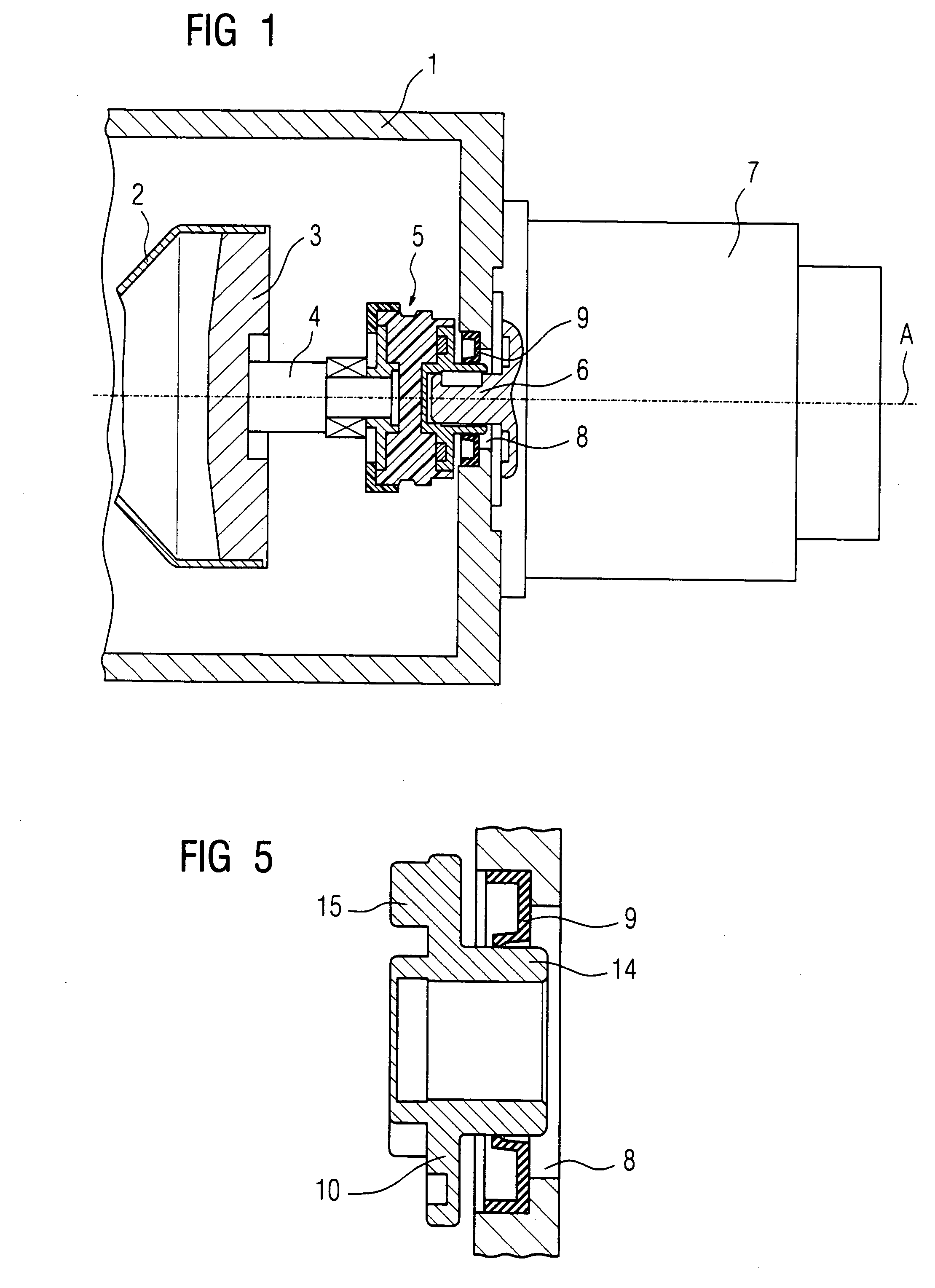
[0019] The principles of the present invention are particularly useful when incorporated in an x-ray radiator which is shown in FIG. 1 and comprises a rotary bulb tube or piston tube 2 which is mounted in the housing 1 filled with a coolant so that it can be rotated around an axis A. A first shaft section 4, which extends from an anode plate 3 of the rotary bulb tube 2, is connected via a coupling, generally indicated at 5, with a second shaft section 6 which extends through a gap 8 provided in the housing 1 to a motor 7.

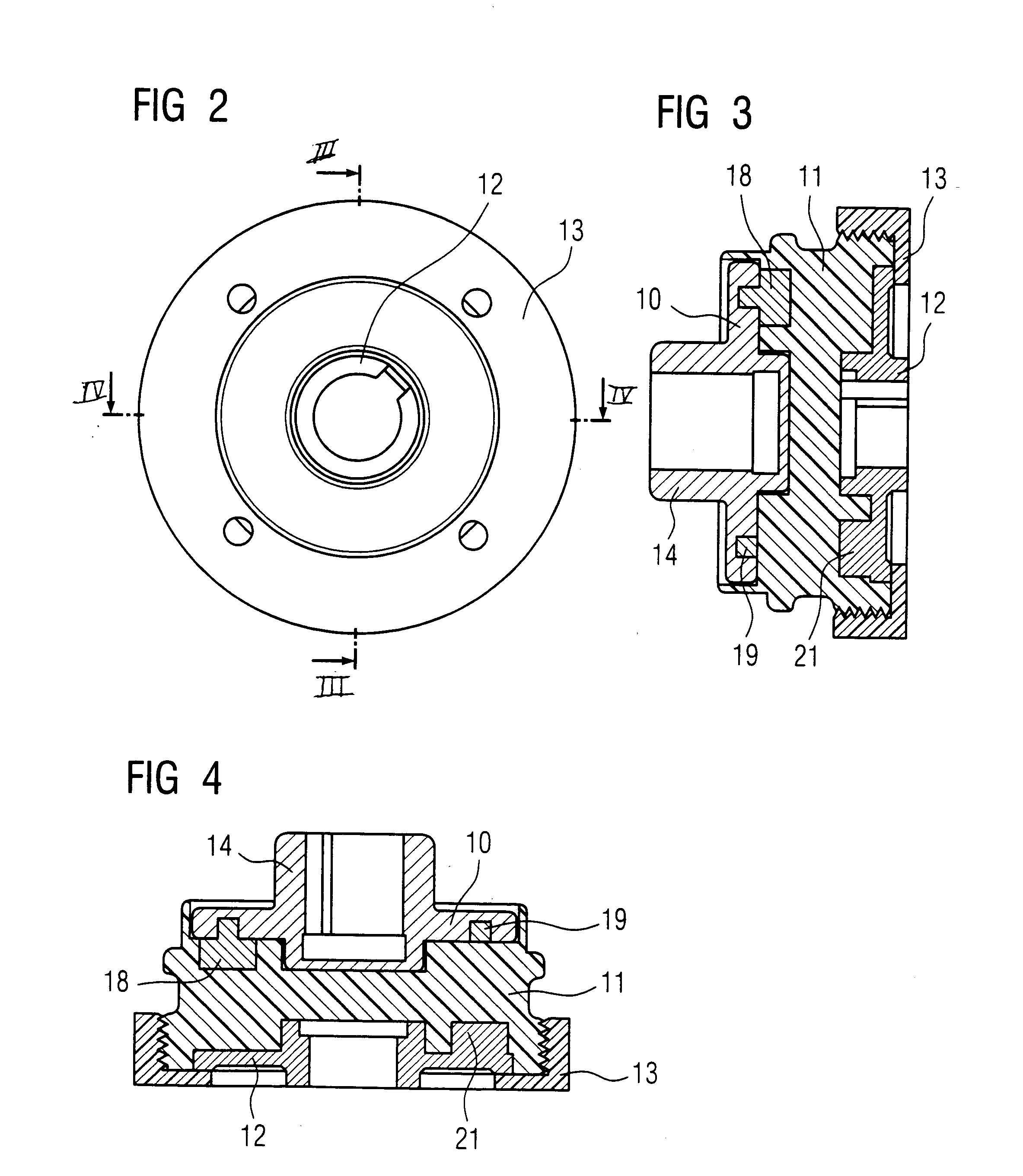
[0020] As illustrated in FIG. 1 through 4, coupling 5 include a drive disc 10 which will be connected to the second shaft section 6. The drive disc 10 is engaged with an intermediate disc 11 which is produced from an electrically insulating substance. The intermediary disc 11 is in turn engaged with an output disc 12 that is connected to the first shaft section 4. The output disc 12 is secured to the intermediate disc 11 by a hasp bushing 13, which, as illustrated ...


PUM


Abstract

A rotary bulb tube of an x-ray radiator is mounted for rotation in a housing, which is filled with a coolant and is connected to a shaft section, which in turn is connected by a coupling to a second shaft section extending to a motor for rotating the bulb tube. The coupling is designed to isolate the rotary bulb tube electrically from the motor and to isolate the bulb tube from motor vibrations.

Description

BACKGROUND OF THE INVENTION [0001] The present invention is directed to an X-ray Radiator in which a rotary bulb tube is rotatably accepted in a housing filled with a coolant and is connected with a shaft. [0002] U.S. Pat. No. 6,396,901, whose disclosure is incorporated by reference thereto, discloses x-ray radiator which comprises a rotary piston tube or rotary bulb tube that is positioned for rotation in a housing filled with a coolant. The rotary bulb tube is driven by means of a motor that is mounted outside of the housing and is connected with the rotary bulb tube via a shaft directed into the housing. A dissipation or leakage of electrical potential occurs in an undesirable manner via the shaft which can impair the function of the motor. Aside from this, vibrations are sometimes transferred to the rotary bulb tube in an undesirable manner. Such vibrations will cause an x-ray beam emitted by the rotary bulb tube to move back and forth in response to these vibrations. Finally, t...

Claims


Application Information

Patent Timeline
Patent Type & Authority Applications(United States)
IPC IPC(8): H01J35/10H01J35/12H01J35/24H01J35/26H01J35/28
CPCH01J35/101H01J2235/1033H01J2235/1006H01J35/305
Inventor GUTHLEIN, FREDDYMAIER, HERMANN
Owner SIEMENS HEALTHCARE GMBH
Why Eureka
Try Eureka