
Machine for removing articles deposited on the ground

a technology for removing articles and machines, which is applied in the direction of clean equipment, gatherer machines, agriculture tools and machines, etc., can solve the problem of not being completely effective in separating debris from sand

Inactive Publication Date: 2005-09-01
H BARBER & SONS
View PDF29 Cites 6 Cited by
  • Summary
  • Abstract
  • Description
  • Claims
  • Application Information

AI Technical Summary

Benefits of technology

"The present invention is a machine that can be used to move debris along the ground. It consists of a wheel unit, a support frame, an endless conveyor with tines, a receptacle for collecting debris, and a mechanism for driving the conveyor. The machine is designed to move debris from one location to another, making it easier to dispose of it."

Problems solved by technology

Although such machines have been effective in removing and collecting such debris, they have been found not to be entirely effective in separating the debris from the sand, returning the sand to the ground and totally capturing the debris in a receptacle for removal to a suitable dump site.

Method used


Image

  • Machine for removing articles deposited on the ground
  • Machine for removing articles deposited on the ground
  • Machine for removing articles deposited on the ground

Examples


Embodiment Construction

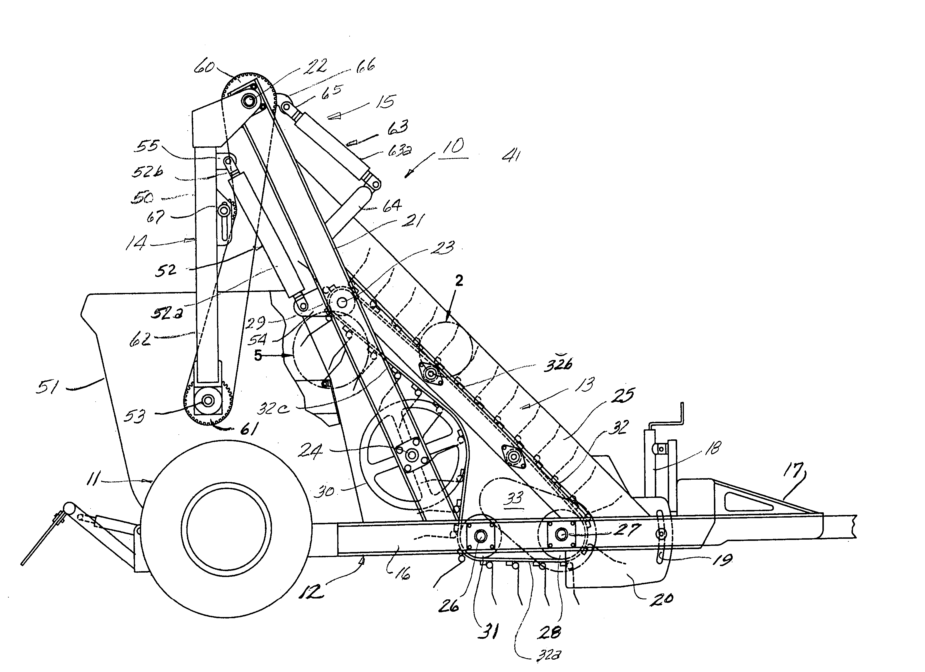
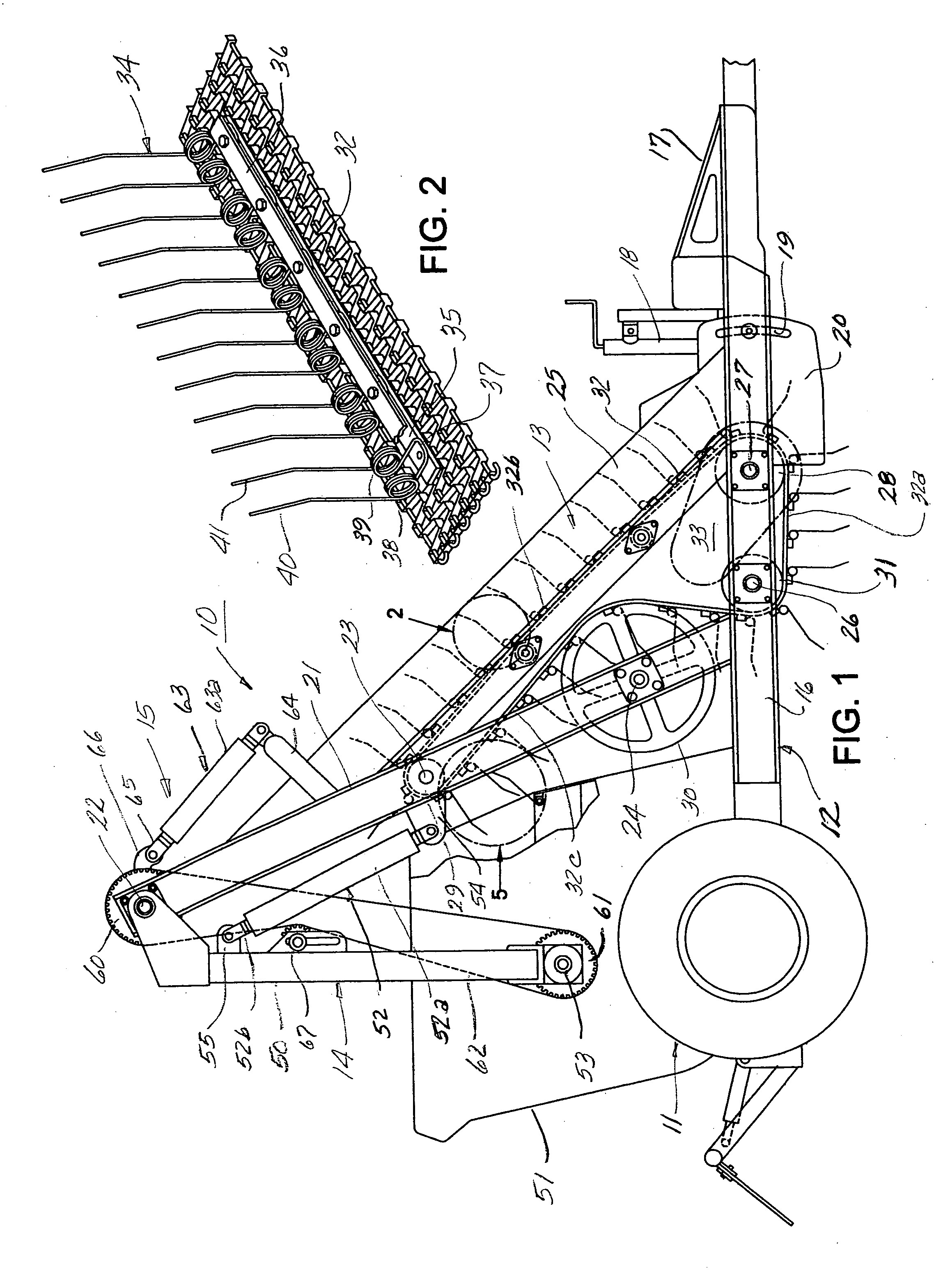
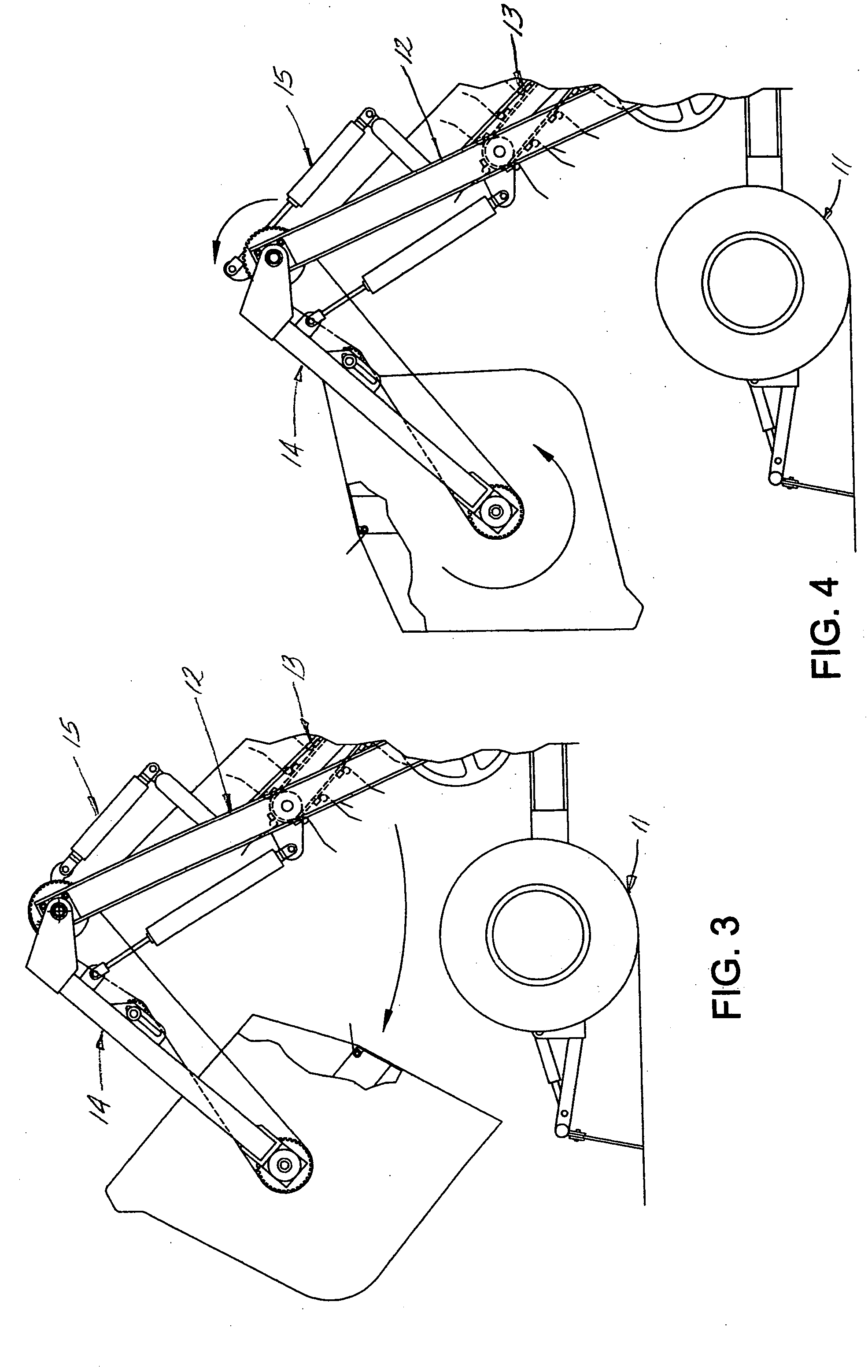
[0009] Referring to the drawings, there is illustrated a machine 10 for removing debris from a tract of sandy ground such as a beach, generally including a wheel unit 11, a support frame 12 mounted on the wheel unit, a conveyor belt assembly 13 mounted on the support frame, a bucket assembly 14 mounted on the rear end of the support frame and cooperable with the conveyor assembly, and bucket tilt assembly 15 mounted on the support frame and cooperable with the bucket assembly. Wheel unit 11 is of a conventional construction including an axle and a pair of wheels. Support frame assembly 12 is supported on the axle of the wheel unit and includes a pair of longitudinal disposed, transversely spaced beams 16, 16 and a set of interconnecting cross beams (not shown). A drawbar 17 is pivotally connected to the front end thereof, which may be detachably connected to a tractor or other prime mover means for towing the machine. The angular relationship of the drawbar to the support frame asse...


PUM


Abstract

A machine for removing articles such as debris and the like deposited on a tract of ground, comprising a wheel unit; a support frame mounted on said wheel unit, having means for advancing said machine along said tract of ground; a endless conveyor mounted on said support frame, having a plurality of tines projecting from an outer side thereof and a flight extending from a front end adjacent ground level, upwardly and inwardly to an elevated rear end; a receptacle mounted on said support frame, positioned to receive articles removed by said tines and carried upwardly and rearwardly on said conveyor and discharged into said receptacle, and having a set of tines cooperable with said conveyor tines to dislodge articles carried by said conveyor tines; and means mounted on said support frame for driving said conveyor.

Description

[0001] This invention relates to a machine for gathering articles deposited on the ground and more particularly to a machine suitable for removing debris strown on sandy tracts of ground such as beaches. The invention further contemplates a machine suitable for use in removing debris from tracts of sandy ground in which the debris is effectively removed from the sand and collected and any sand removed in such process is returned to the ground. BACKGROUND OF THE INVENTION [0002] In the prior art, a number of machines have been developed for removing debris from the ground and particularly machines for removing debris strown on sandy beaches. Typically, such machines have been towed by a tractor, and have included an endless conveyor extending upwardly and rearwardly, means for directing debris and some accompanying sandy earth onto an upper, forwardly disposed flight of the conveyor, and a receptacle for receiving debris carried by the conveyor and discharged at an upper, rearward en...

Claims


Application Information

Patent Timeline
Patent Type & Authority Applications(United States)
IPC IPC(8): B07C5/36
CPCE01H12/00
Inventor GERAGHTY, WILLIAM F.
Owner H BARBER & SONS
Learn More