Slurry expressing and liquid displacing device

a technology of liquid displacing and slurry, which is applied in the direction of sedimentation settling tanks, separation processes, filtration separation, etc., can solve the problems of low efficiency, low rate, and relatively long operating time, and achieve shortening the path of displacing, shortening the time required for operation, and increasing separation efficiency

Inactive Publication Date: 2005-09-01
LIUNG FENG INDAL
View PDF3 Cites 23 Cited by
  • Summary
  • Abstract
  • Description
  • Claims
  • Application Information

AI Technical Summary

Benefits of technology

[0006] Accordingly, an object of the present invention is to provide a slurry expressing and liquid displacing device in which the direction of slurry treatment and the separated effluence of slurry are radially configured thereby shortening the path of displacing and so shortening the time required for operation and increasing separating efficiency through high transportation rate.

Problems solved by technology

However, the constructions of the separating devices disclosed at above mentioned US patents have a common shortage that the transportation direction of slurry and the separated effluence of slurry are axially configured.
Thus, during the course of effluence-solid separation, the slurry has to pass through a relatively long treatment path and so the operating time is relatively long.
Furthermore, the slurry is transported by gravity in the above mentioned US patents, and so the transportation rate is low, which results in the low efficiency.

Method used


Image

  • Slurry expressing and liquid displacing device
  • Slurry expressing and liquid displacing device
  • Slurry expressing and liquid displacing device

Examples


Embodiment Construction

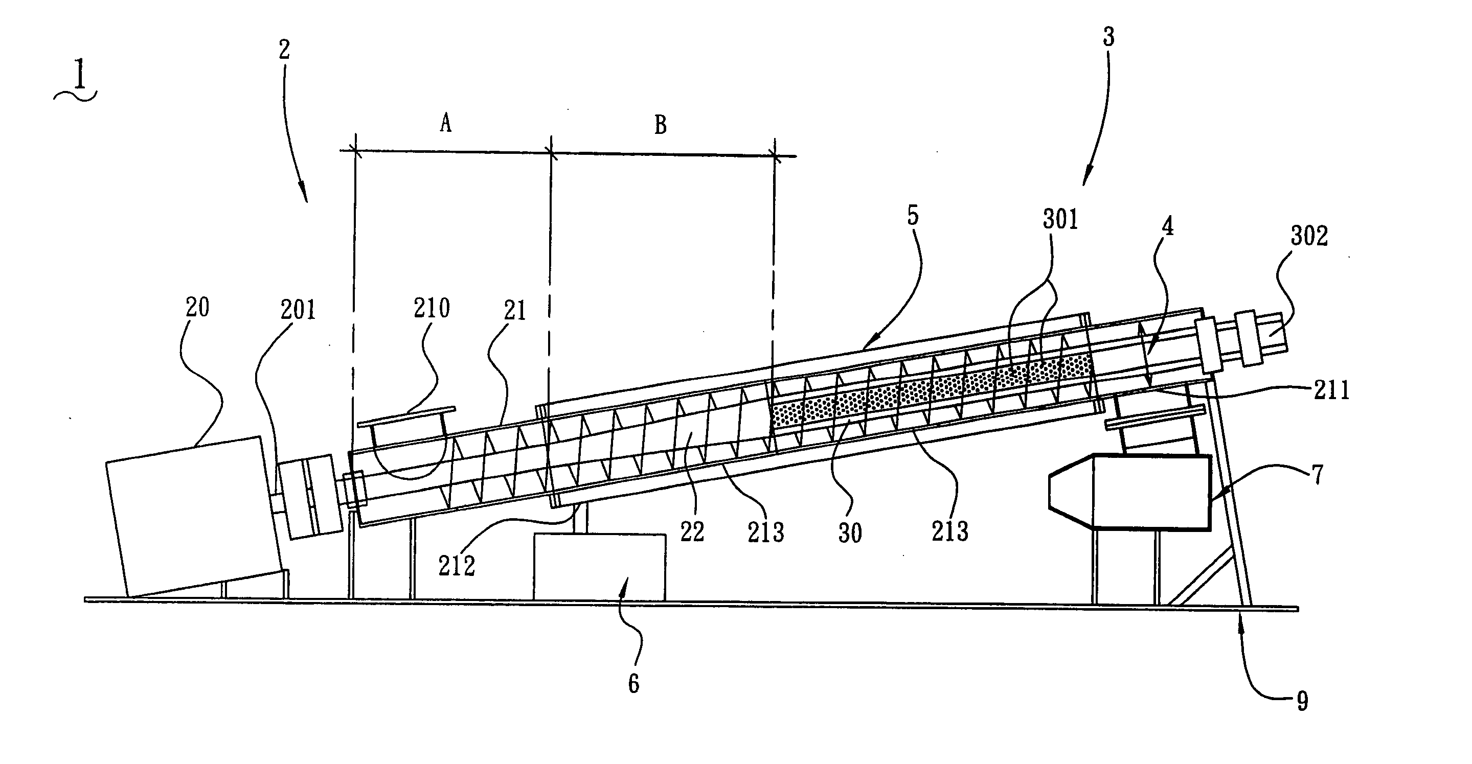
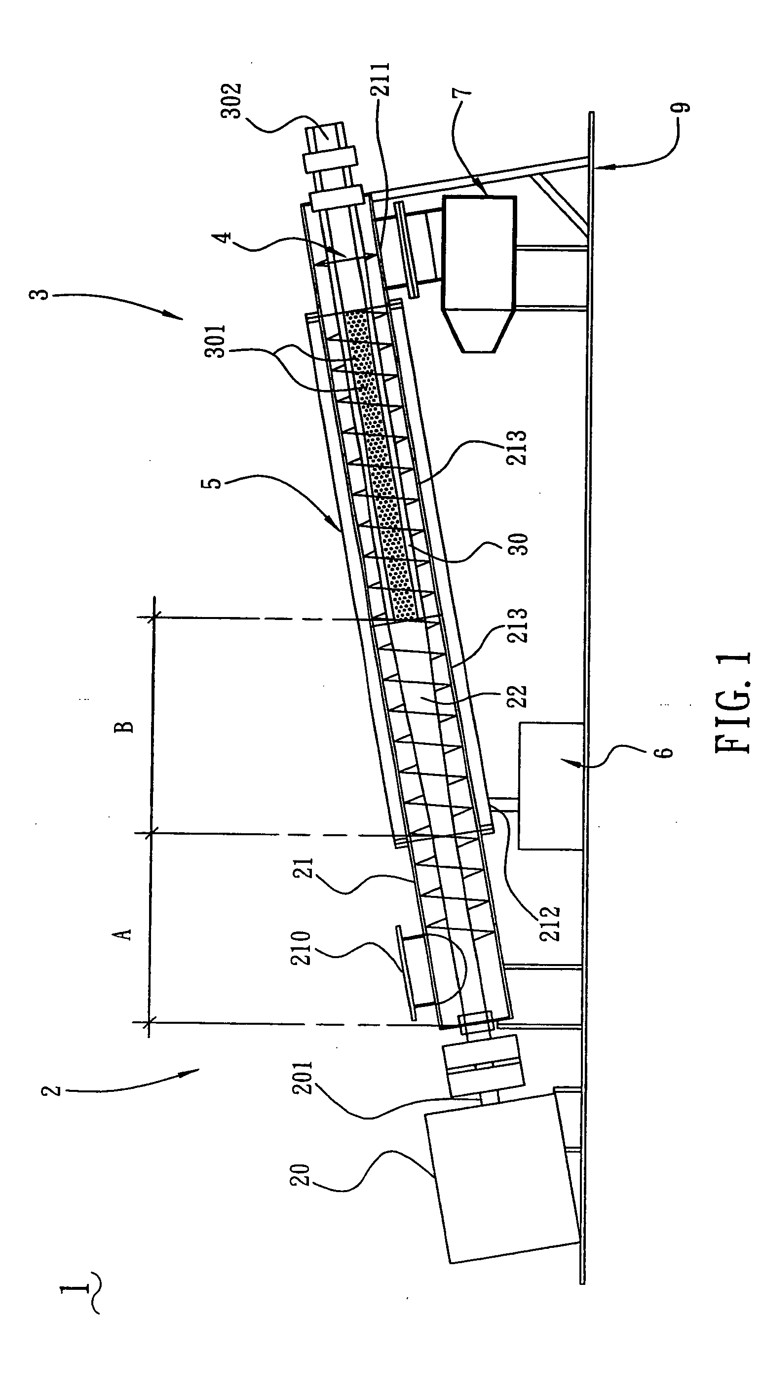
[0011] Referring to FIG. 1, a slurry expressing and liquid displacing device 1 in accordance with a first embodiment of the present invention is mounted on a slanting bracket 9 and includes a expressing mechanism 2, a displacing mechanism 3, a blender 4, a collecting tube 5 and first and second storage troughs 6, 7. The expressing mechanism 2 includes a driving motor 20, a transportation tube 21, and a first helical transmission shaft 22. The driving motor 20 is mounted on one end of the slanting bracket 9 with an axes 201 thereof rotatably connected with an end of the first helical transmission shaft 22. The transportation tube 21 has an inlet 210 at an end thereof near the driving motor 20 for slurry to flow into the transportation tube 21, and an outlet 211,212 at the other end thereof for separated effluence and solid of the slurry to flow out from the transportation tube 21. The second storage trough 7 is disposed under the outlet 211 for collecting the solid. The first storage...


PUM

PropertyMeasurementUnit
radial pore volumeaaaaaaaaaa
diametersaaaaaaaaaa
slanting angleaaaaaaaaaa

Abstract

The present invention provides a slurry expressing and liquid displacing device which is used to express slurry and then separate out effluence and solid of the slurry through radial pore volume displacement of continuous filtration and washing for getting high purity solid. The slurry expressing and liquid displacing device includes a expressing mechanism, a displacing mechanism, a blender, a collecting tube, and first and second storage troughs. The expressing mechanism includes a first helical transmission shaft having a compression zone for transporting and efficiently compressing the slurry. The displacing mechanism includes a second helical transmission shaft rotatably connected with the first helical transmission for connecting with displacing liquid such as water. A plurality of through holes is disposed at the side surface of the second helical transmission shaft to radially spray through for facilitating the displacing liquid to flow out therethrough. Thus effluence and solid of the slurry are efficiently separated out thereby shortening the time required for operation and increasing separating efficiency.

Description

BACKGROUND OF THE INVENTION [0001] 1. Field of the Invention [0002] The present invention relates to a slurry expressing and liquid displacing device, and particularly to a slurry expressing and liquid displacing device which expresses slurry and then separates out effluence and solid of the slurry through radial continuous filtration and washing for getting high purity solid. [0003] 2. Prior Art [0004] One method that has been used for separating a mixture into solid and liquid component, is a separating apparatus which includes a filter permeable to the liquid component against which the mixture is urged to separate the liquid component. The solid component is substantially scraped from the filter wall, as for example as shown in U.S. Pat. Nos. 3,587,859, 4,491,462, 4,705,624, 6,467,305 and so on. [0005] However, the constructions of the separating devices disclosed at above mentioned US patents have a common shortage that the transportation direction of slurry and the separated e...

Claims


Application Information

Patent Timeline
Patent Type & Authority Applications(United States)
IPC IPC(8): B01D29/33B01D29/35B01D29/64B30B9/12B30B9/14
CPCB01D29/33B30B9/121B30B9/128B30B9/14B01D29/35B01D29/54B01D29/6476B01D29/828
Inventor LIN, HENG-ICHUANG, FENG-MINGLIN, HSU TSANG
Owner LIUNG FENG INDAL
Why Eureka
Try Eureka