Rack mount for flat panel display

Inactive Publication Date: 2005-09-01
ACTION ELECTRONICS
View PDF7 Cites 4 Cited by
  • Summary
  • Abstract
  • Description
  • Claims
  • Application Information

AI Technical Summary

Benefits of technology

[0004] The present invention also provides a rack mount for mounting a flat panel display therein. The

Problems solved by technology

However, the conventional rack for mounting or installing the television is typically very large and heavy.
It is also very dangerous for tall people.
Such type of rack is not suitable for use

Method used


Image

  • Rack mount for flat panel display
  • Rack mount for flat panel display
  • Rack mount for flat panel display

Examples


Example

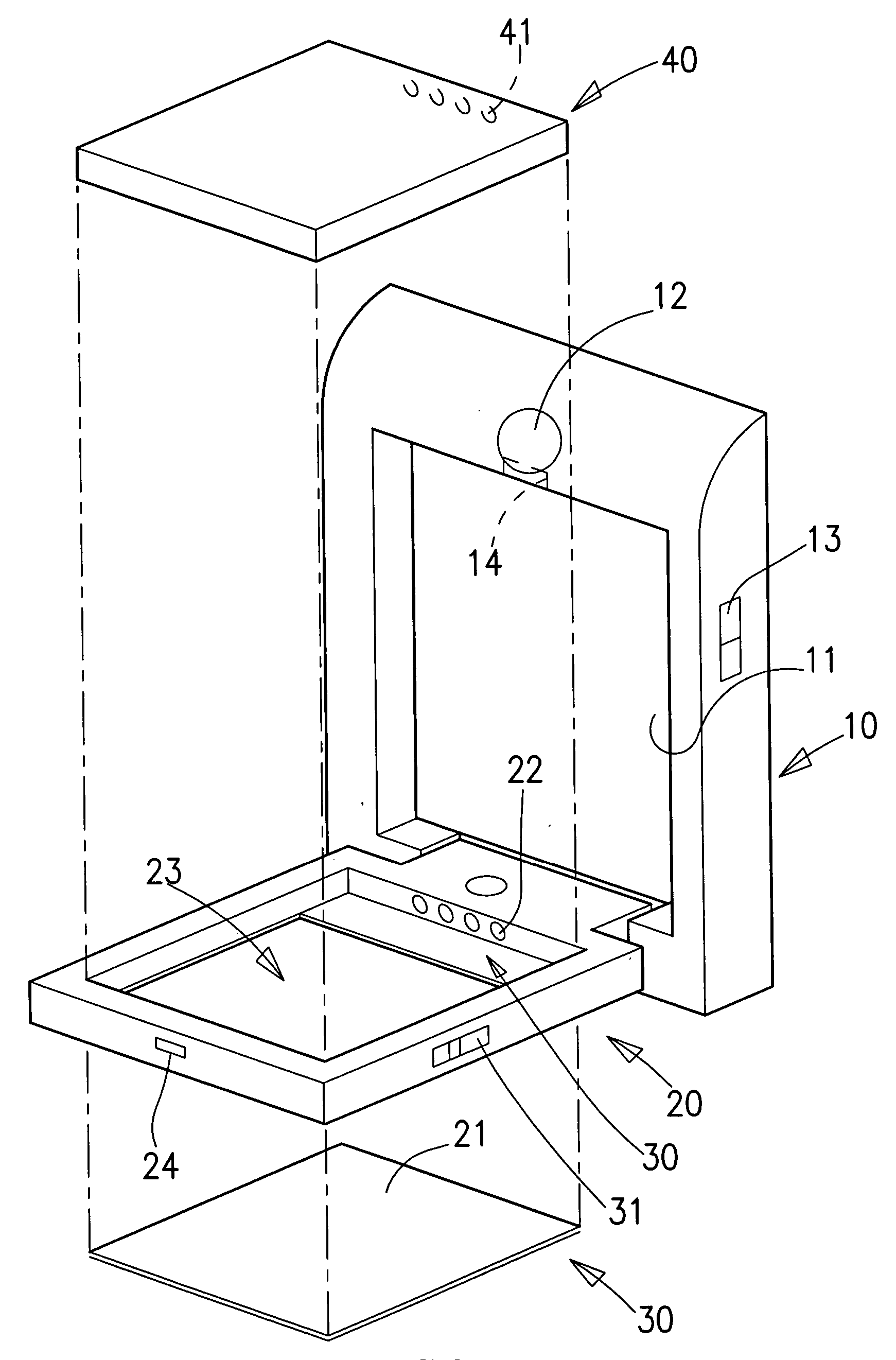
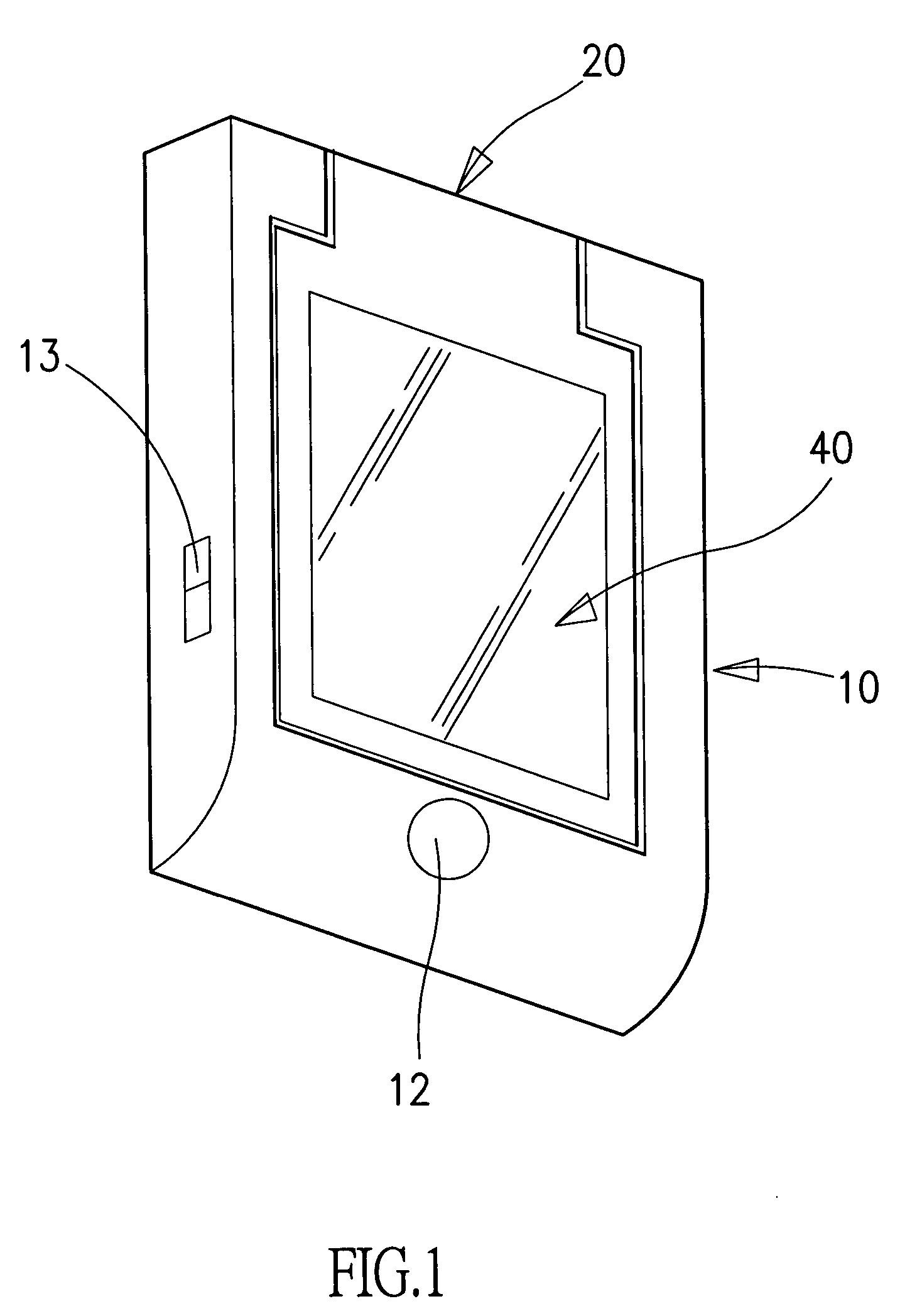
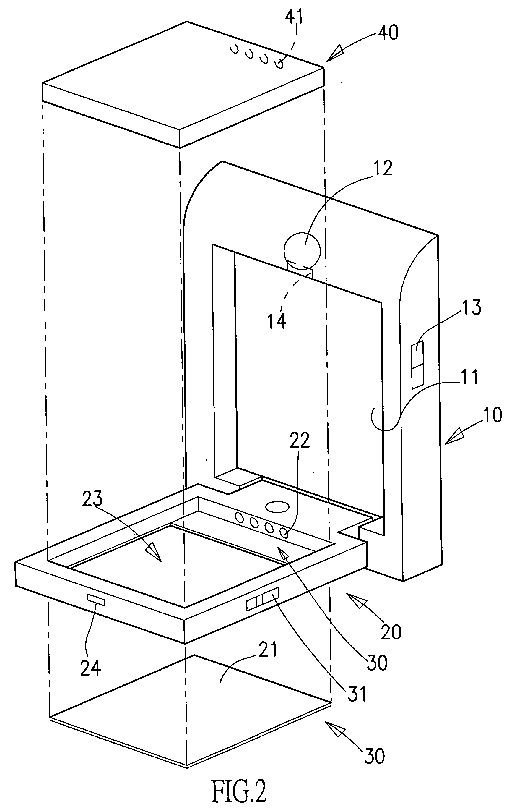
[0011] Referring now to the drawings wherein the showings are for purpose of illustrating preferred embodiments of the present invention only, and not for purposes of limiting the same. As shown in FIGS. 1-2, the present invention provides a rack mount for mounting a flat panel display or a mirror. The rack mount structure includes a roof mount 10, a suspending frame 20, an illumination device 30 and a display device 40. The roof mount 10 includes a slot 11, a release button 12 and a power switch 13. The slot 11 includes a male latching member 14 controlled by the release button 12. The suspending frame 20 is pivotally connected to one side of the roof mount 10. As shown, suspending frame 20 includes a receiving space 23 for accommodating the display device 40 therein. One side of the receiving space 23 may be covered by a glass or mirror surface 21. The mirror surface 21 can be attached to the suspending frame 20 by glue or other adhering or installation kit. The suspending frame 2...


PUM


Abstract

A rack mount includes a roof mount and a suspending frame. The roof mount has a slot therein and the suspending frame is pivotally connected to one side of the slot, such that the suspending frame is operative to rotate between 0° and 180° with respect to the mount roof. The suspending frame has a receiving space for mounting a flat panel display therein. A mirror surface or display surface is attached to a bottom surface of the suspending frame. The rack mount further has an illumination device installed on the roof mount or the suspending frame, and a switch accessible to the user for controlling on/off status of the illumination device. Alternatively, the illumination device can be activated by the orientation of the suspending frame with respect to the roof mount.

Description

BACKGROUND OF THE INVENTION [0001] The present invention relates in general to a rack mount, and more particularly, to a rack mount fitted on a roof of a vehicle or a location for mounting a flat panel display operative to provide both audio and video display functions. [0002] Vehicles have become the major transportation tool for modern society. For large buses, televisions are often mounted on top of the bus for entertaining passengers. However, the conventional rack for mounting or installing the television is typically very large and heavy. It is thus very easy for it to block the view of both the passengers and the driver. It is also very dangerous for tall people. Such type of rack is not suitable for use in a small size family car. In the small size car, the television is typically in the form of a liquid crystal display embedded in the middle of the dashboard. Therefore, it is not convenient for the passengers in the back seats to watch. Further, mirrors have been commonly f...

Claims


Application Information

Patent Timeline
IPC IPC(8): A47F5/08B60R11/02
CPCB60R11/0235
Inventor PENG, JUEN-TIEN
Owner ACTION ELECTRONICS
Why Eureka
Try Eureka