
Fuser temperature control providing faster wake up from cold start by optimizing standby temperature of fuser roller

a technology of temperature control and fuser roller, which is applied in the direction of electrographic process apparatus, instruments, optics, etc., can solve the problems of re-attaching toner from print sheet to fuser roller, possibly overheating of fuser roller, etc., and achieves no deficiency in temperature of fuser roller. , the effect of quick heating

Active Publication Date: 2005-09-01
BROTHER KOGYO KK
View PDF4 Cites 20 Cited by
  • Summary
  • Abstract
  • Description
  • Claims
  • Application Information

AI Technical Summary

Benefits of technology

[0012] It is therefore an object of the present invention to provide a technique of controlling the temperature of the fuser roller that allows reduction in length of time during which the user is required to wait until a printing operation starts during a cold start, and / or that allows avoidance of overheating of the print sheet.
[0020] As is evident from the above description, the above apparatus is configured, such that the heat-storing period for applying heat to the fuser roller for heat storage is provided. Further, the above apparatus is operated, such that the temperature of the fuser roller is maintained during the heat-storing period in the event of the cold start, at the second standby-temperature higher than the normal standby-temperature. As-a result, the whole fuser unit is warmed up quicker than when the temperature of the fuser roller is maintained at the normal standby-temperature.
[0021] The above apparatus is operated, such that the fuser unit is adequately warmed up with the temperature being at the second standby-temperature, with the result that deficiency in temperature of the fuser roller is not caused where the temperature of the fuser roller is raised up to the desired fusing temperature in response to issue of a print request from the user.
[0022] The above apparatus is configured, such that the second standby-temperature is set so as to be lower than the fusing temperature established for a fusing operation of the fuser unit, resulting in avoidance of re-attachment of a toner from the receiver medium to the fuser roller due to overheating of the receiver medium.

Problems solved by technology

The inventor's research on the above two approaches has revealed that, the former approach suffers from a drawback that the user of the image forming apparatus is forced to wait for a prolonged time until a printing operation starts, and the latter approach suffers from a drawback that the fuser roller is possibly overheated due to application of too much heat to the print sheet, possibly resulting in re-attachment of a toner from the print sheet to the fuser roller.

Method used


Image

  • Fuser temperature control providing faster wake up from cold start by optimizing standby temperature of fuser roller
  • Fuser temperature control providing faster wake up from cold start by optimizing standby temperature of fuser roller
  • Fuser temperature control providing faster wake up from cold start by optimizing standby temperature of fuser roller

Examples


first embodiment

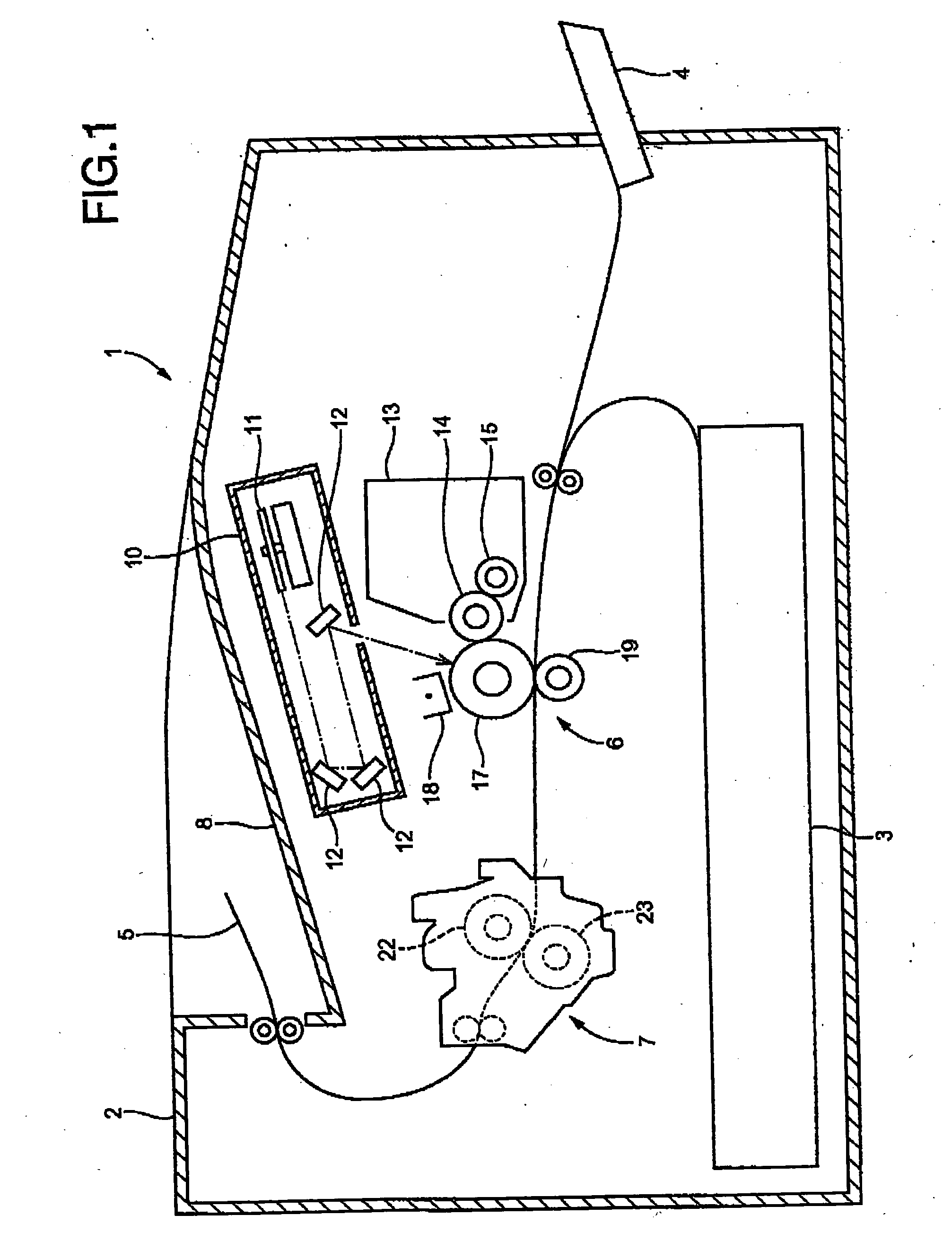
[0114]FIG. 1 shows schematically in sectional view a laser printer 1 as an image forming apparatus in accordance with the present invention.

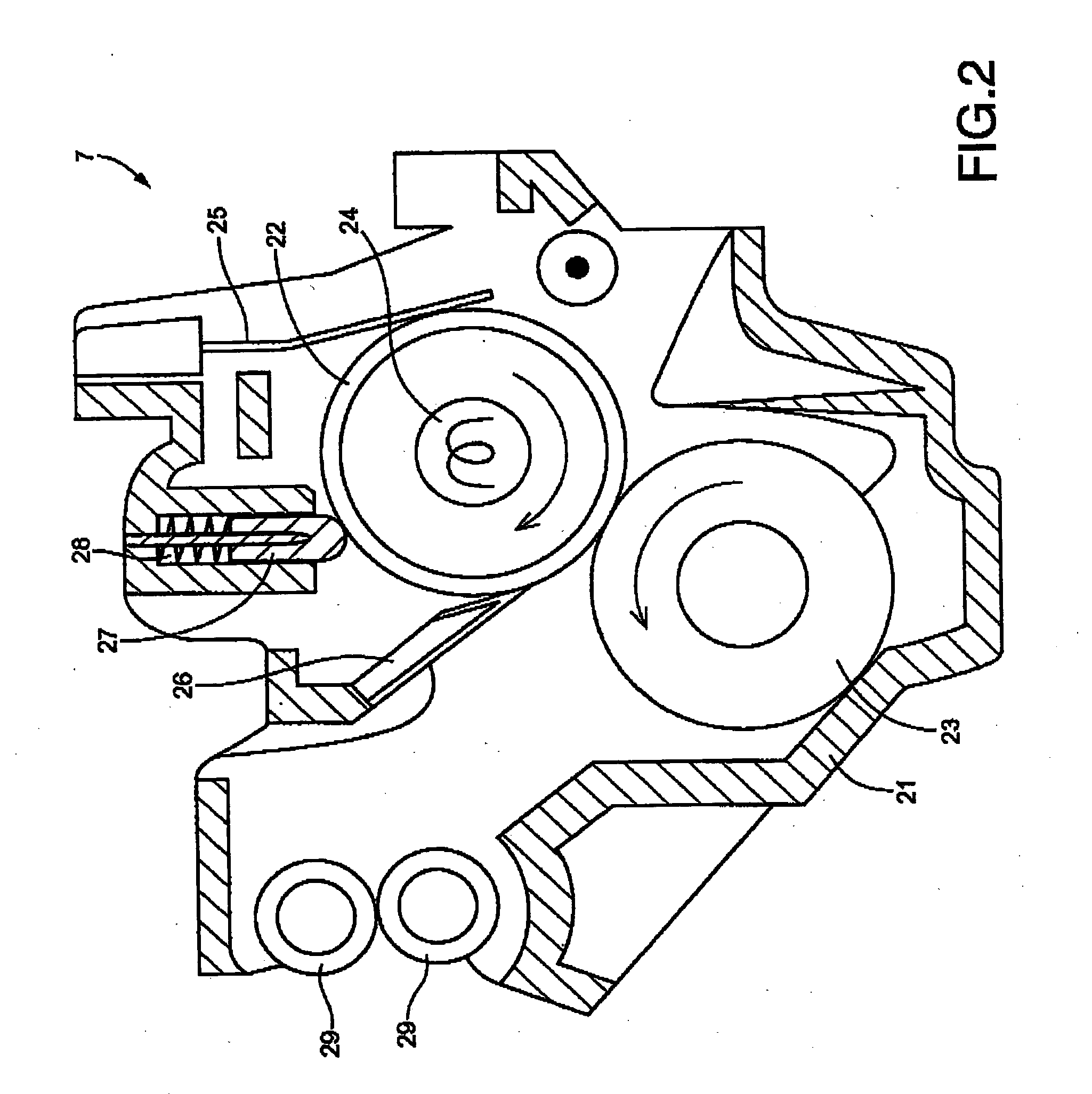
[0115] The laser printer 1 has a body casing 2, and a first tray 3 and a second tray 4 which are disposed in the lower portion of the body casing 2. In the laser printer 1, an image forming unit 6 forms a toner image on a print sheet 5 which is an example of a receiver medium supplied from a selected one of the first tray 3 and the second tray 4. By a fuser unit 7, a fusing operation is then performed to fuse the toner image with heat, and the print sheet 5 is finally delivered to an exit tray 8 disposed at the top of the body casing 2.

[0116] The image forming unit 6 is constructed so as to include: a scanning unit 10; a process cartridge 13; a photoconductive drum 17; a charger 18; a transfer roller 19, etc.

[0117] The scanning unit 10, which is disposed at the top of the body casing 2, includes: a laser light emitter not shown; a polygon mirr...

second embodiment

[0234] Then, with reference to FIGS. 13 and 14, a laser printer constructed according to the present invention will be described.

[0235] Described in comparison with the first embodiment, the present embodiment is largely common to the first embodiment in the hardware and software construction, while the present embodiment differs from the first embodiment only in the software-implemented elements for establishment of the desired temperature in the “second standby-mode.”

[0236] In view of the above, the common elements of the present embodiment to those of the first embodiment will be referenced the same names or the same reference numerals as those in the description and illustration of the first embodiment, without a redundant description and illustration, while the different elements of the present embodiment from those of the first embodiment will be described in more detail.

[0237]FIG. 13 illustrates in graph the temporal change in the surface temperature T of the fuser roller 22...


PUM


Abstract

An apparatus is disclosed which is for forming an image using a fuser unit, including: a fuser roller; a heater heating the fuser roller; a temperature sensor detecting a temperature of the fuser roller; and a controller controlling the heater to substantially achieve a desired temperature of the fuser roller, wherein the controller includes a desired-temperature setting device. The device is operated during a cold start of the fuser unit, so as to set the desired temperature to a second standby-temperature which is lower than a fusing temperature and higher than a normal standby-temperature, so as to maintain the desired temperature at the second standby-temperature during a heat-storing period during which heat is stored in the fuser unit, and so as to set the desired temperature to the normal standby-temperature upon termination of the heat-storing period.

Description

[0001] This application is based on Japanese Patent Application No. 2004-056491 filed Mar. 1, 2004, the content of which is incorporated hereinto by reference. CROSS-REFERENCE TO RELATED APPLICATIONS [0002] Not Applicable. BACKGROUND OF THE INVENTION [0003] 1. Field of the Invention [0004] The present invention relates to a technique employed in an image forming apparatus such as a laser printer, and more particularly to a technique of controlling the temperature of a fuser roller fusing an image to a receiver medium such as a print sheet. [0005] 2. Description of the Related Art [0006] Typically, an image forming apparatus such as a laser printer is operated in combination with a fuser unit. The fuser unit is provided for heating a print sheet bearing an unfused toner thereon and then fusing the toner image to the print sheet. [0007] The above fusing unit is typically configured to include: a fuser roller incorporating a heater therein; a pressure roller disposed in pressure contac...

Claims


Application Information

Patent Timeline
Patent Type & Authority Applications(United States)
IPC IPC(8): G03G21/00G03G15/20
CPCG03G15/205
Inventor DAN, KENICHI
Owner BROTHER KOGYO KK
Features
  • Generate Ideas
  • Intellectual Property
  • Life Sciences
  • Materials
  • Tech Scout
  • Unparalleled Data Quality
  • Higher Quality Content
  • 60% Fewer Hallucinations
Learn More