[0019]In one embodiment, a
chemical vapor deposition system is provided which includes an entrance
isolator operable to prevent contaminants from entering the
system at an entrance of the
system; an exit
isolator operable to prevent contaminants from entering the system at an exit of the system; and an intermediate
isolator disposed between the entrance and exit isolators. The system may further include a first deposition zone disposed adjacent the entrance isolator and a second deposition zone disposed adjacent the exit isolator. The intermediate isolator is disposed between the deposition zones and is operable to prevent mixing of gases between the first deposition zone and the second deposition zone.
[0020]In one embodiment, the entrance isolator is further operable to prevent
back diffusion of gases injected into the first deposition zone, the intermediate isolator is further operable to prevent
back diffusion of gases injected into the second deposition zone, and the exit isolator is further operable to prevent
back diffusion of gases injected into the second deposition zone. An isolation zone formed by at least one of the isolators has a length between 1 to 2 meters. A gas, such as
nitrogen, is injected into the entrance isolator at a first flow rate, such as about 30 liters per minute, to prevent back
diffusion of gases from the first deposition zone. A gas, such as
arsine, is injected into the intermediate isolator at a first flow rate, such as about 3 liters per minute, to prevent back mixing of gases between the first deposition zone and the second deposition zone. A gas, such as
nitrogen, is injected into the exit isolator at a first flow rate, such as about 30 liters per minute, to prevent contaminants from entering the system at the exit of the system. In one embodiment, an exhaust is disposed adjacent each isolator and operable to exhaust gases injected by the isolators. An exhaust may be disposed adjacent each deposition zone and operable to exhaust gases injected into the deposition zones.
[0029]In one embodiment, a method for forming multiple epitaxial
layers on a substrate using a
chemical vapor deposition system is provided which includes introducing the substrate into a guide path, such as a channel, at an entrance of the system, while preventing contaminants from entering the system at the entrance; depositing a first epitaxial layer on the substrate, while the substrate moves along the channel of the system; depositing a second epitaxial layer on the substrate, while the substrate moves along the channel of the system; preventing mixing of gases between the first deposition step and the second deposition step; and retrieving the substrate from the channel at an exit of the system, while preventing contaminants from entering the system at the exit. The method may further include heating the substrate prior to depositing the first epitaxial layer; maintaining the temperature of the substrate as the first and second epitaxial
layers are deposited on the substrate; and / or cooling the substrate after depositing the second epitaxial layer. The substrate may substantially float along the channel of the system. The first epitaxial layer may include aluminum
arsenide and / or the second epitaxial layer may include
gallium arsenide. In one embodiment, the substrate substantially floats along the channel of the system. The method may further include depositing a phosphorous
gallium arsenide layer on the substrate and / or heating the substrate to a temperature within a range from about 300
degree Celsius to about 800 degrees Celsius during the depositing of the epitaxial
layers. A center temperature to an edge temperature of the substrate may be within 10 degrees Celsius of each other.
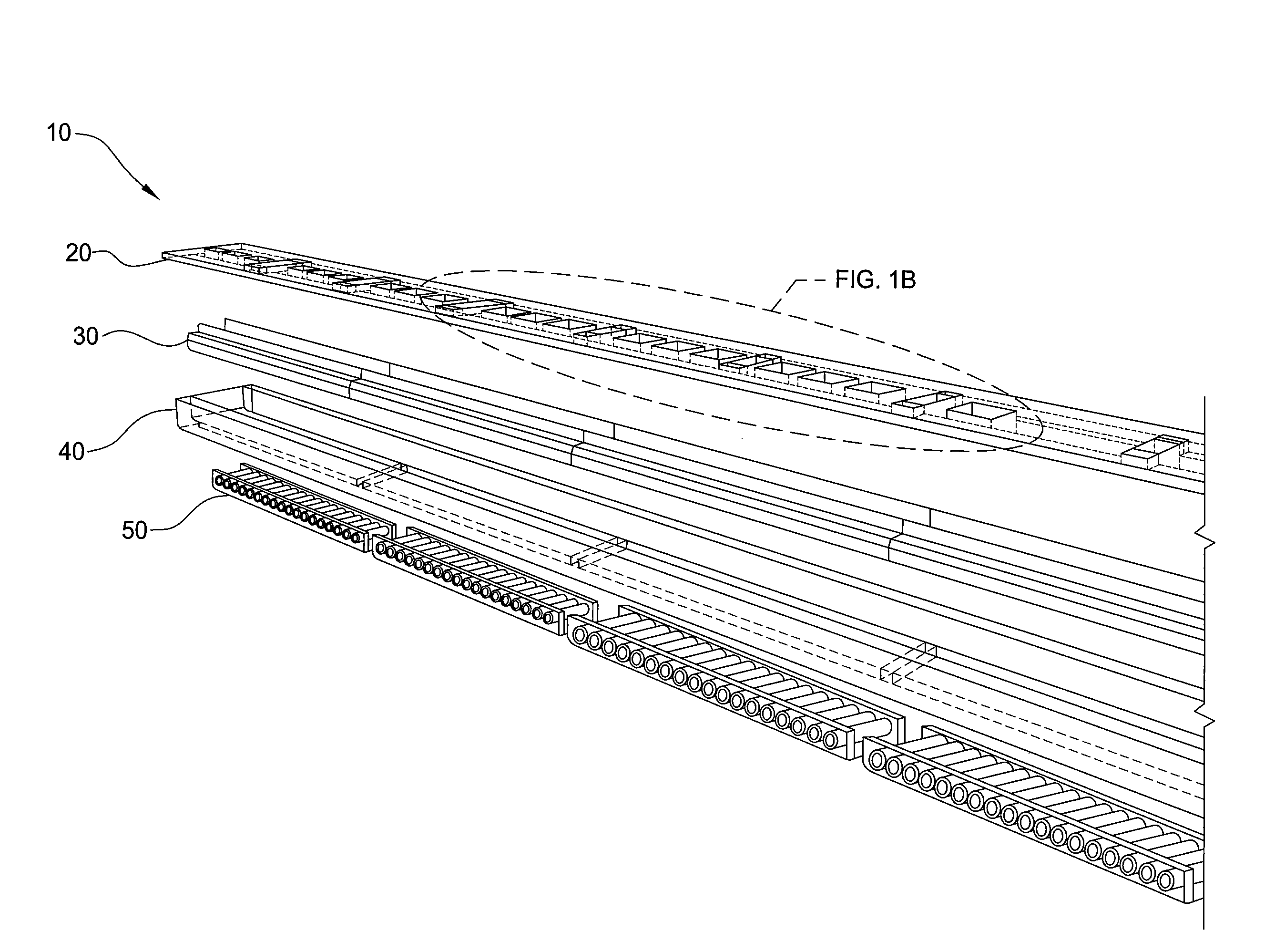
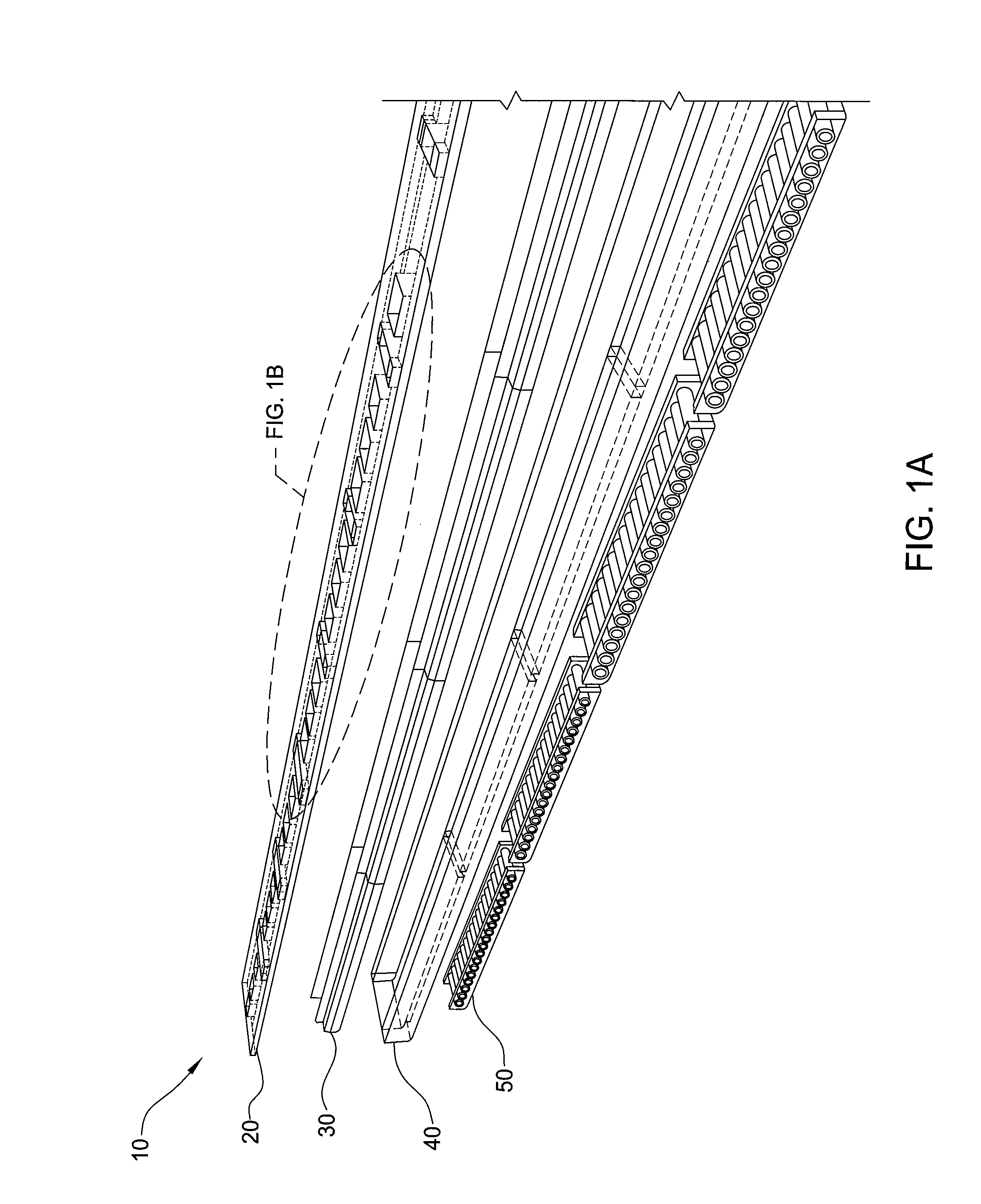
[0031]In one embodiment, a chemical vapor deposition system is provided which includes a entrance isolator operable to prevent contaminants from entering the system at an entrance of the system; an exit isolator operable to prevent contaminants from entering the system at an exit of the system; and a intermediate isolator disposed between the entrance and exit isolators. The system may further include a first deposition zone disposed adjacent the entrance isolator and a second deposition zone disposed adjacent the exit isolator. The intermediate isolator is disposed between the deposition zones and is operable to prevent mixing of gases between the first deposition zone and the second deposition zone. A gas is injected into the entrance isolator at a first flow rate to prevent back
diffusion of gases from the first deposition zone, a gas is injected into the intermediate isolator at a first flow rate to prevent back mixing of gases between the first deposition zone and the second deposition zone, and / or a gas is injected into the exit isolator at a first flow rate to prevent contaminants from entering the system at the exit of the system. An exhaust may be disposed adjacent each isolator and operable to exhaust gases injected by the isolators and / or disposed adjacent each deposition zone and operable to exhaust gases injected into the deposition zones.

