Thermostat and method for operating in either a normal or dehumidification mode

a technology of dehumidification mode and thermostat, which is applied in the field of thermostats, can solve the problems of reducing speed and not cooling the space as effectively, and achieve the effect of optimum comfort and improved dehumidification

Inactive Publication Date: 2006-11-23
EMERSON ELECTRIC CO
View PDF7 Cites 78 Cited by
  • Summary
  • Abstract
  • Description
  • Claims
  • Application Information

AI Technical Summary

Benefits of technology

[0003] In accordance with the principles of the present invention, various embodiments of a thermostat for controlling a variable capacity cooling system are provided. One embodiment of a thermostat comprises a processor for receiving input signals from a temperature sensor and humidity sensor for sensing the temperature and humidity within the space, and responsively providing for operation in a first mode to operate the compressor and operate the blower at less than full capacity when the sensed temperature and sensed humidity are above the desired temperature and humidity set points, and in a second mode to operate the compressor at full capacity and the blower at full capacity when the sensed temperature is more than a predetermined amount above the desired temperature set point. The first mode of operating the compressor at maximum capacity and the blower at less than maximum capacity provides improved dehumidification when the humidity level in the space is above the desired humidity set point. The second mode of operating the compressor at maximum capacity and the blower at maximum capacity provides full cooling capacity when the sensed temperature is more than a predetermined amount above the temperature set point, regardless of whether the humidity level is above the desired humidity set point. The thermostat of the present invention automatically switches between the first mode of operation and second mode of operation as necessary to maintain the desired temperature while also offering humidity control to provide optimum comfort to the occupant.

Problems solved by technology

However, a thermostat providing such a dehumidification mode for operating the blower at a reduced speed will not cool the space as effectively as when the blower is at high speed.
The resulting uncomfortable temperature would consequently force the occupant to input a request to this type of thermostat to manually override the dehumidification operating mode.

Method used


Image

  • Thermostat and method for operating in either a normal or dehumidification mode
  • Thermostat and method for operating in either a normal or dehumidification mode
  • Thermostat and method for operating in either a normal or dehumidification mode

Examples


Embodiment Construction

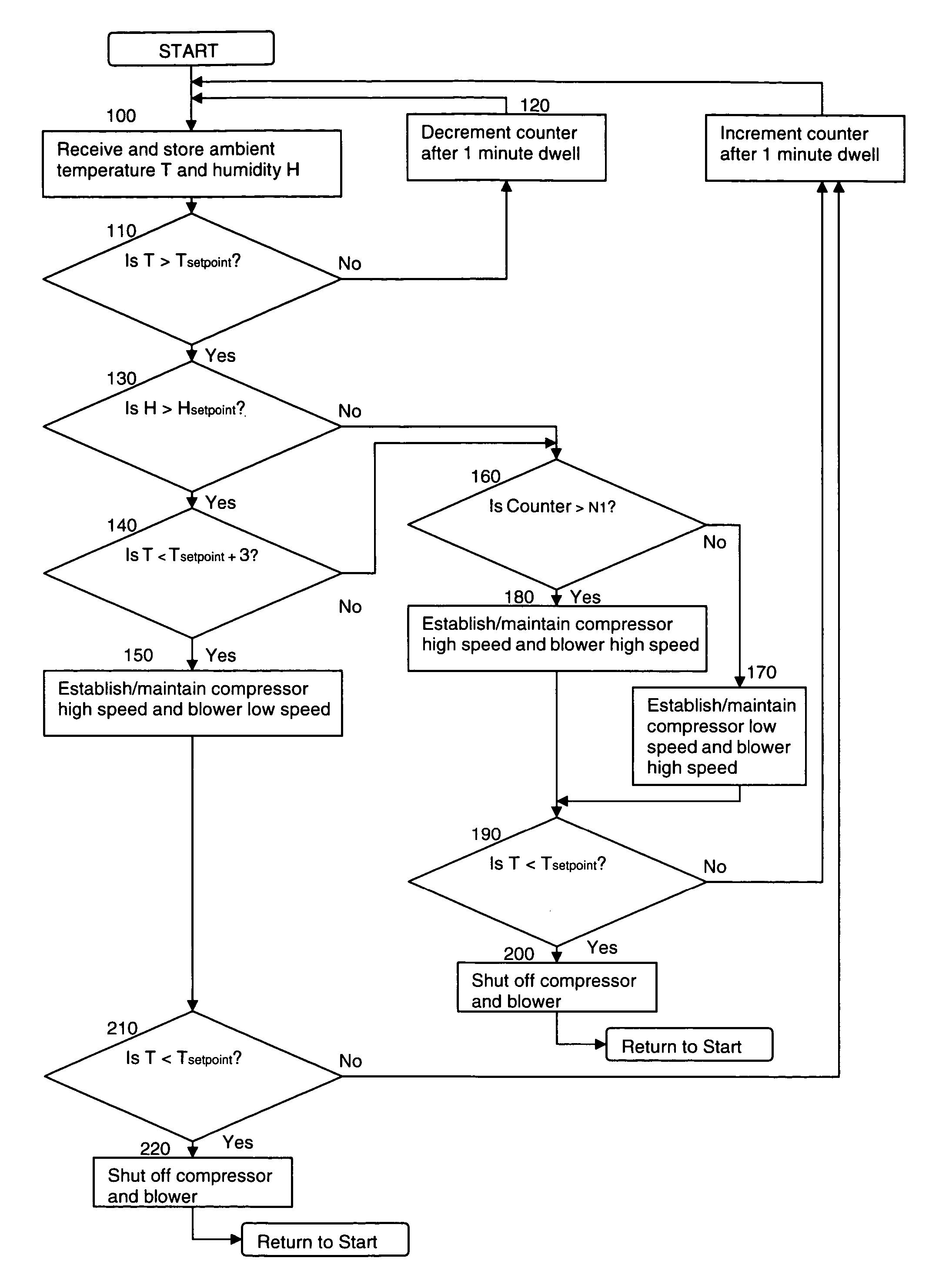
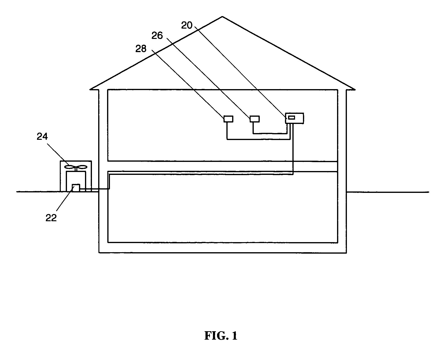
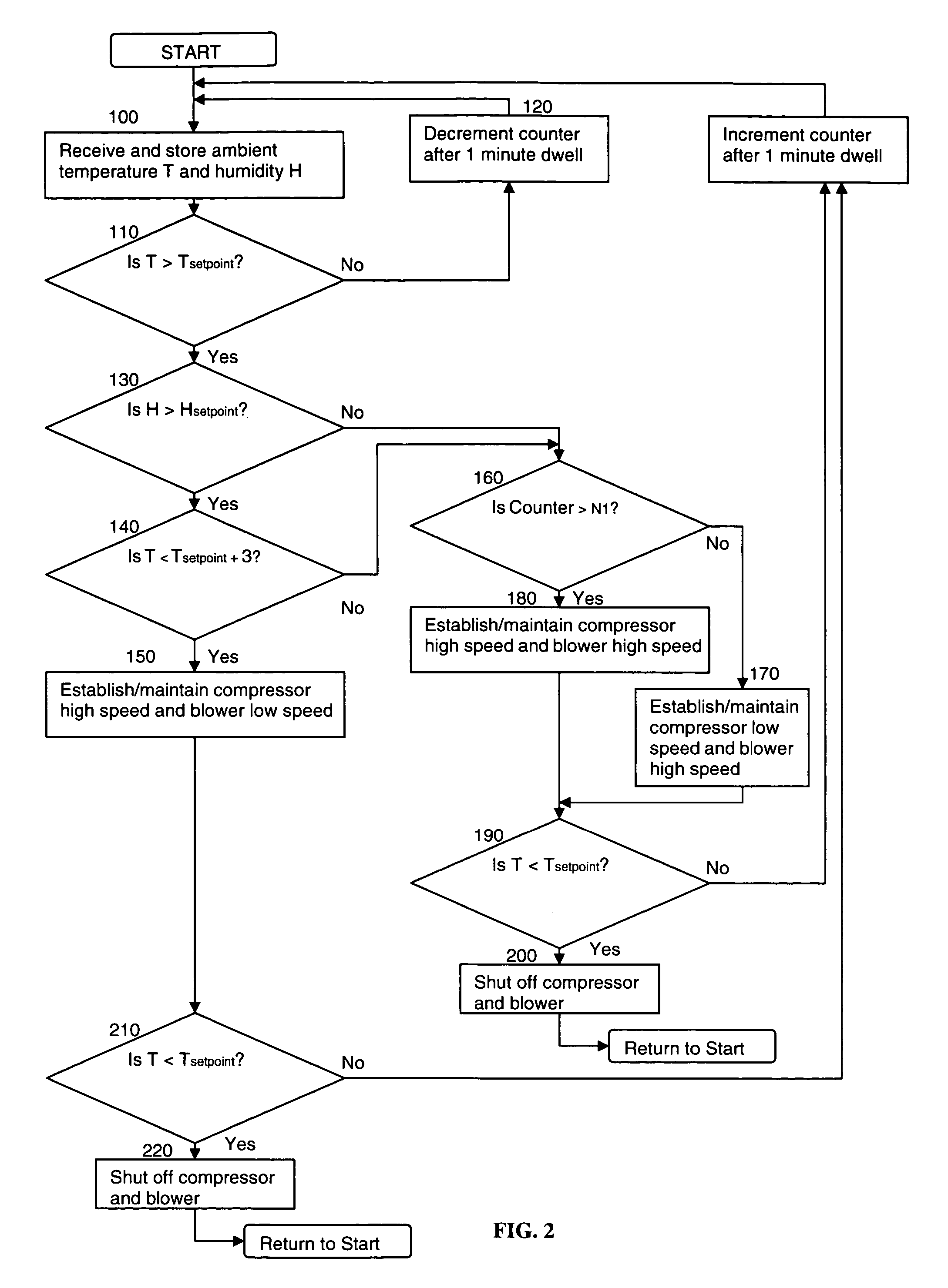
[0009] A thermostat for controlling a climate control system in which embodiments of the present invention can be implemented is indicated generally as 20 in FIG. 1. The climate control system includes an air conditioning system having a compressor unit 22 and a blower unit 24 each of which is capable of operating at full capacity and at less than full capacity. The thermostat 20 controls the operation of the air conditioning system via connections to a compressor motor and a blower motor. The thermostat 20 further comprises an internal or external temperature sensor 26 and an internal or external humidity sensor 28 for sensing the temperature and humidity within the space conditioned by the air conditioning system. In one embodiment, the thermostat 20 comprises a processor for receiving input signals from the temperature sensor and humidity sensor. The thermostat is also configured to enable an occupant to provide input to the processor of a desired temperature set point and a desi...


PUM


Abstract

The inventive thermostat provides for sensing the temperature and humidity within the space, and responsively controlling the operation of an air conditioning compressor and blower to maintain the desired temperature and humidity. In a first mode, the thermostat operates the compressor at maximum capacity and the blower at less than maximum capacity to provide dehumidification when the humidity level is above a set point. In a second mode, the thermostat operates the compressor and blower at maximum capacity to provide full cooling capacity when the sensed temperature is more than a predetermined amount above the desired temperature setting. The thermostat is also configured to automatically switch from the first mode of operation to the second mode of operation.

Description

BACKGROUND OF THE INVENTION [0001] The present invention relates to thermostats, and in particular, to thermostats used for controlling climate control systems that include a multi-stage air conditioning system. [0002] Thermostats are used to control climate control systems to maintain the temperature of the space conditioned by the climate control system. The typical thermostat compares the sensed temperature of the space with a set point temperature and activates the climate control system to heat or cool the space to the desired set point temperature. Some climate control systems include a multi-stage cooling system that comprises a two speed compressor and a two speed indoor circulator blower. This dual speed cooling system can operate the compressor at a low speed when the demand for cooling is low, and at a high speed when the demand for cooling is high. Likewise, the indoor circulator blower may be operated at a high speed for maximum cooling or at a low speed for improved de...

Claims


Application Information

Patent Timeline
Patent Type & Authority Applications(United States)
IPC IPC(8): F25B49/00F25B1/00
CPCF24F3/1405F24F11/001F24F11/0012F24F11/0015Y02B30/746F24F2003/1446F25B2600/0253G05D27/02Y02B30/741F24F11/0079F24F11/30F24F2110/00F24F2110/10F24F2110/20F24F11/77Y02B30/70F24F11/86F24F11/65
Inventor CAREY, STEVEN L.MUELLER, CARL J.TOTH, BARTHOLOMEW L.
Owner EMERSON ELECTRIC CO
Why Eureka
Try Eureka