Expansion valve with a distributor
a distributor and expansion valve technology, applied in the direction of valve operating means/release devices, refrigeration components, light and heating equipment, etc., can solve the problem of difficult control of the flow of refrigerant, and achieve the effect of increasing dehumidification and increasing refrigeration capacity
- Summary
- Abstract
- Description
- Claims
- Application Information
AI Technical Summary
Benefits of technology
Problems solved by technology
Method used
Image
Examples
first embodiment
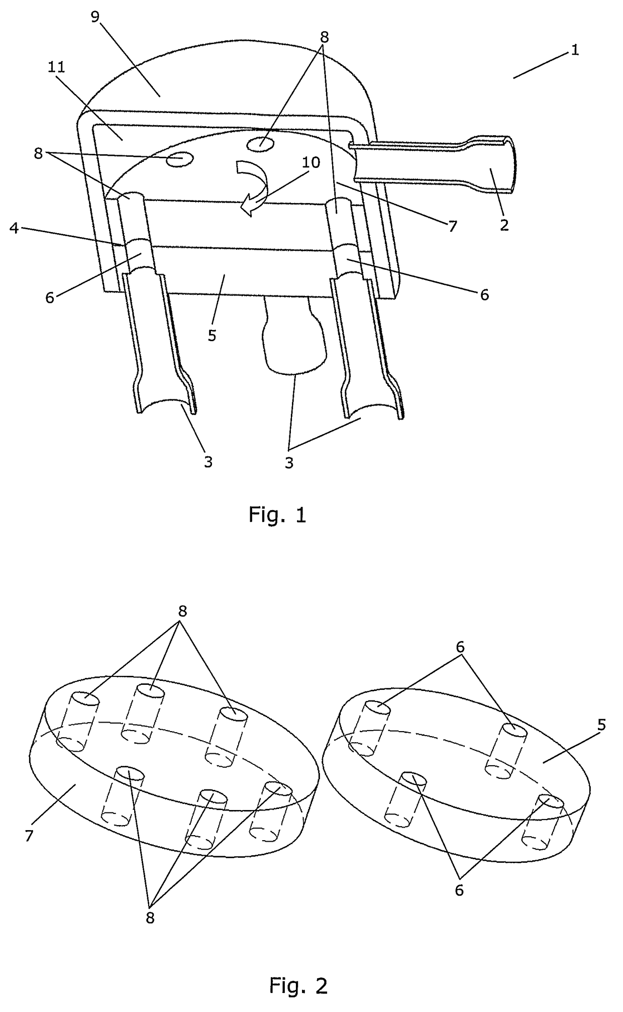
[0069]FIG. 1 is a perspective view of a cut through an expansion valve 1 according to the invention. The expansion valve 1 comprises an inlet opening 2 adapted to receive fluid medium in a liquid state. Thus, the inlet opening 2 is connectable to a source of fluid medium in a liquid state. The expansion valve 1 further comprises four outlet openings 3, three of which are visible, the outlet openings 3 being arranged fluidly in parallel.
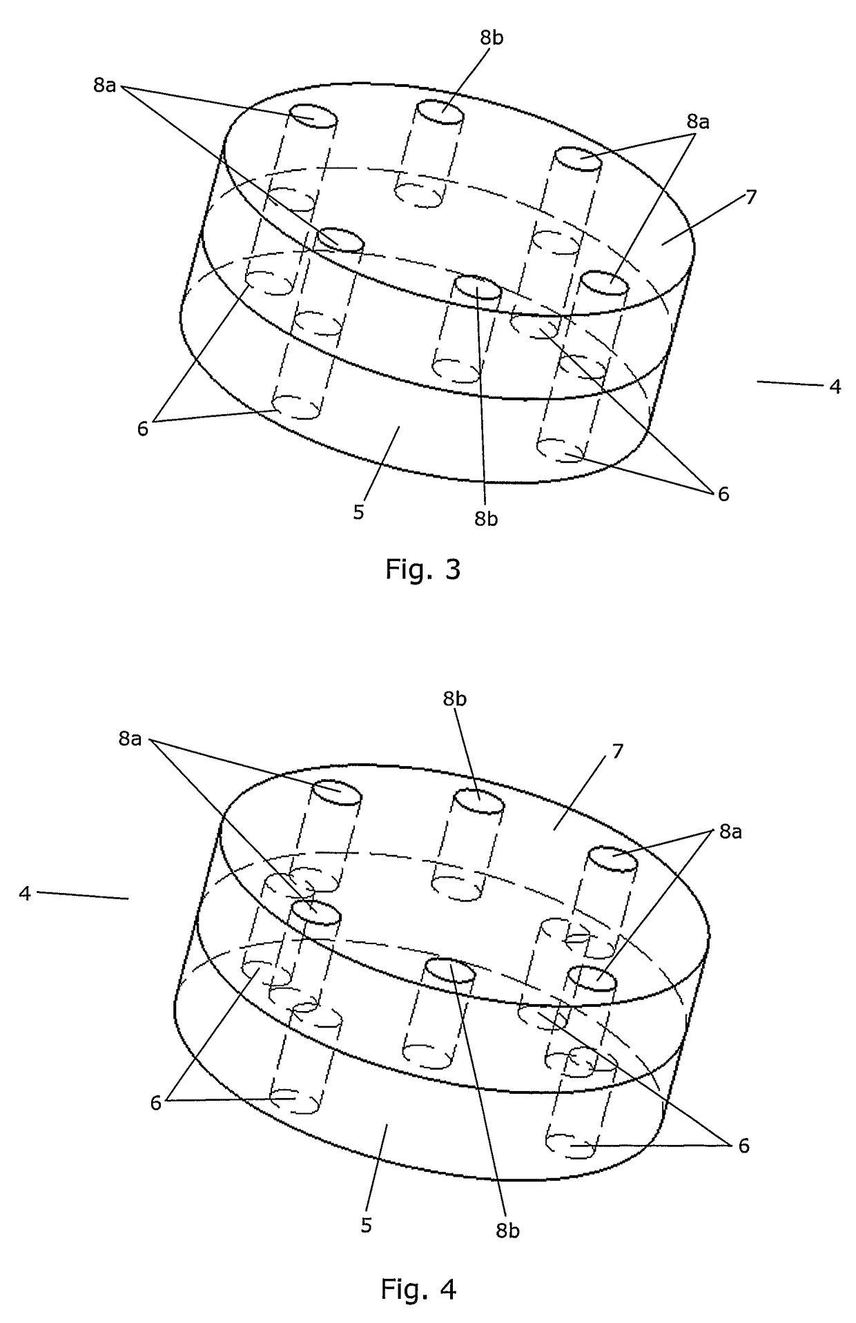
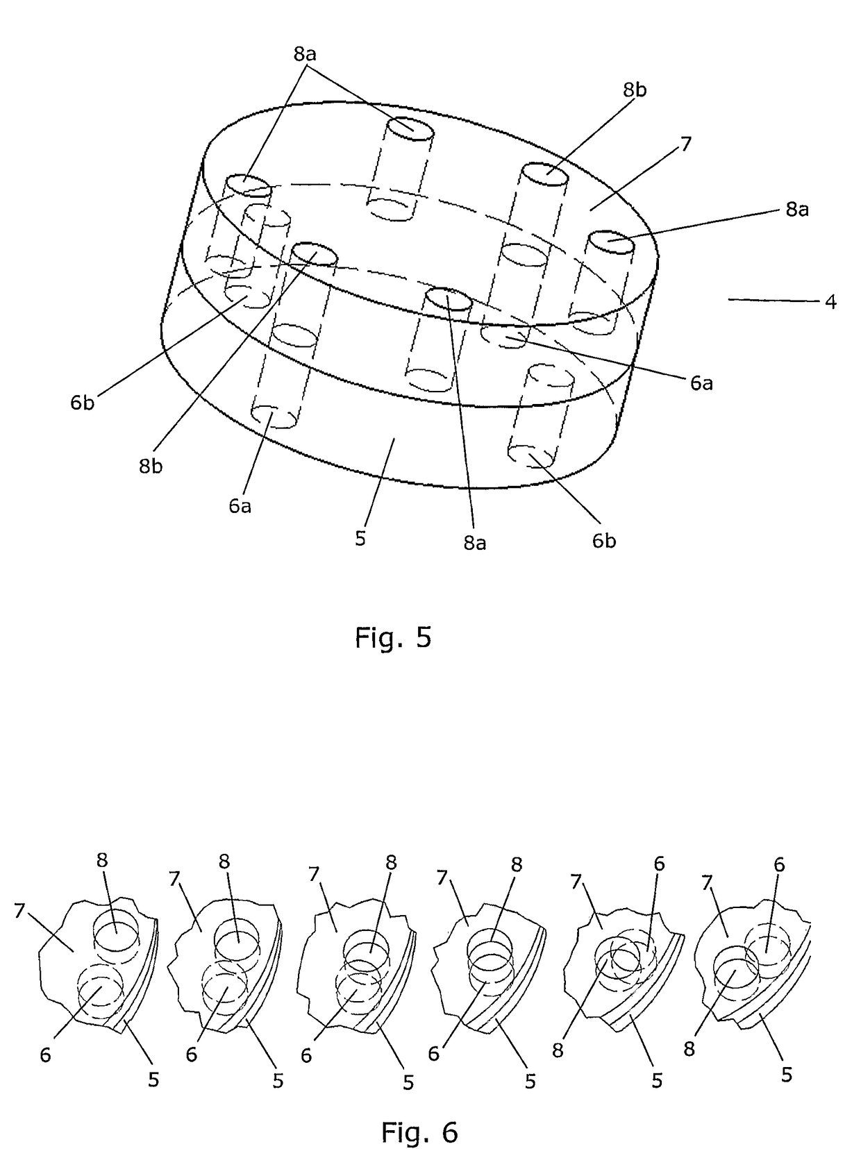
[0070]The expansion valve 1 further comprises a distributor 4 comprising an orifice disk 5 being provided with four openings 6, three of which are visible, and a distributor disk 7 being provided with six openings 8, four of which are visible. The orifice disk 5 is mounted fixedly relative to the outlet openings 3, and each of the openings 6 is arranged at a position corresponding to an outlet opening 3. The distributor disk 7 is arranged rotatably relative to the orifice disk 5 and to a housing 9 of the expansion valve 1, as indicated by arrow 10. Th...
second embodiment
[0080]FIG. 10 is a perspective view of a cut through an expansion valve 1 according to the invention. Similarly to the embodiment shown in FIG. 1, the expansion valve 1 of FIG. 10 comprises an inlet opening 2 and four outlet openings 3, three of which are visible, the outlet openings 3 being arranged fluidly in parallel.
[0081]The expansion valve 1 further comprises a distributor 4 comprising an orifice plate 12 having four valve seats 13 formed therein, three of which are visible. Each of the valve seats 13 is arranged in fluid connection with one of the outlet openings 3.
[0082]The distributor 4 further comprises a movable disk 14 having four valve elements 15 arranged thereon. Two of the valve elements 15 are visible in FIG. 10. Each of the valve elements 15 is arranged at a position corresponding to the position of a valve seat 13. Accordingly, each valve seat 13 / valve element 15 pair forms a valve which is arranged to control fluid flow to an outlet opening 3.
[0083]The movable di...
third embodiment
[0087]FIG. 14 is a perspective view of a cut through an expansion valve 1 according to the invention. The expansion valve 1 of FIG. 14 comprises an inlet opening 2 adapted to receive fluid medium in a liquid state. Thus, the inlet opening 2 is connectable to a source of fluid medium in a liquid state. The expansion valve 1 further comprises six outlet openings 3 being arranged fluidly in parallel.
[0088]The expansion valve 1 further comprises a distributor 4 comprising a cam shaft 18 and six valve seat 13 / valve element 15 pairs, each being fluidly connected to an outlet opening 3. The cam shaft 18 is arranged in abutment with the valve elements 15, and each of the valve elements 15 is biased in a direction towards the cam shaft 18, thereby ensuring tight abutment between the cam shaft 18 and the valve elements 15.
[0089]The cam shaft 18 is arranged rotatably about a centre axis 19. It is shaped in such a manner that the radius of the cross section of the cam shaft 18 varies as a funct...
PUM
 Abstract
Description
Claims
Application Information
 - R&D
- Intellectual Property
- Life Sciences
- Materials
- Tech Scout
- Unparalleled Data Quality
- Higher Quality Content
- 60% Fewer Hallucinations
Browse by: Latest US Patents, China's latest patents, Technical Efficacy Thesaurus, Application Domain, Technology Topic, Popular Technical Reports.
© 2025 PatSnap. All rights reserved.Legal|Privacy policy|Modern Slavery Act Transparency Statement|Sitemap|About US| Contact US: help@patsnap.com


