Utility lighter with safety device

Inactive Publication Date: 2005-09-08
WONG CHI LAM
View PDF4 Cites 9 Cited by
  • Summary
  • Abstract
  • Description
  • Claims
  • Application Information

AI Technical Summary

Benefits of technology

[0016] Another object of the present invention is to provide a utility lighter comprising a safety device which does not employ any compli

Problems solved by technology

Moreover, the urging force is of such a magnitude that an ordinary child is incapa

Method used


Image

  • Utility lighter with safety device
  • Utility lighter with safety device
  • Utility lighter with safety device

Examples


Example

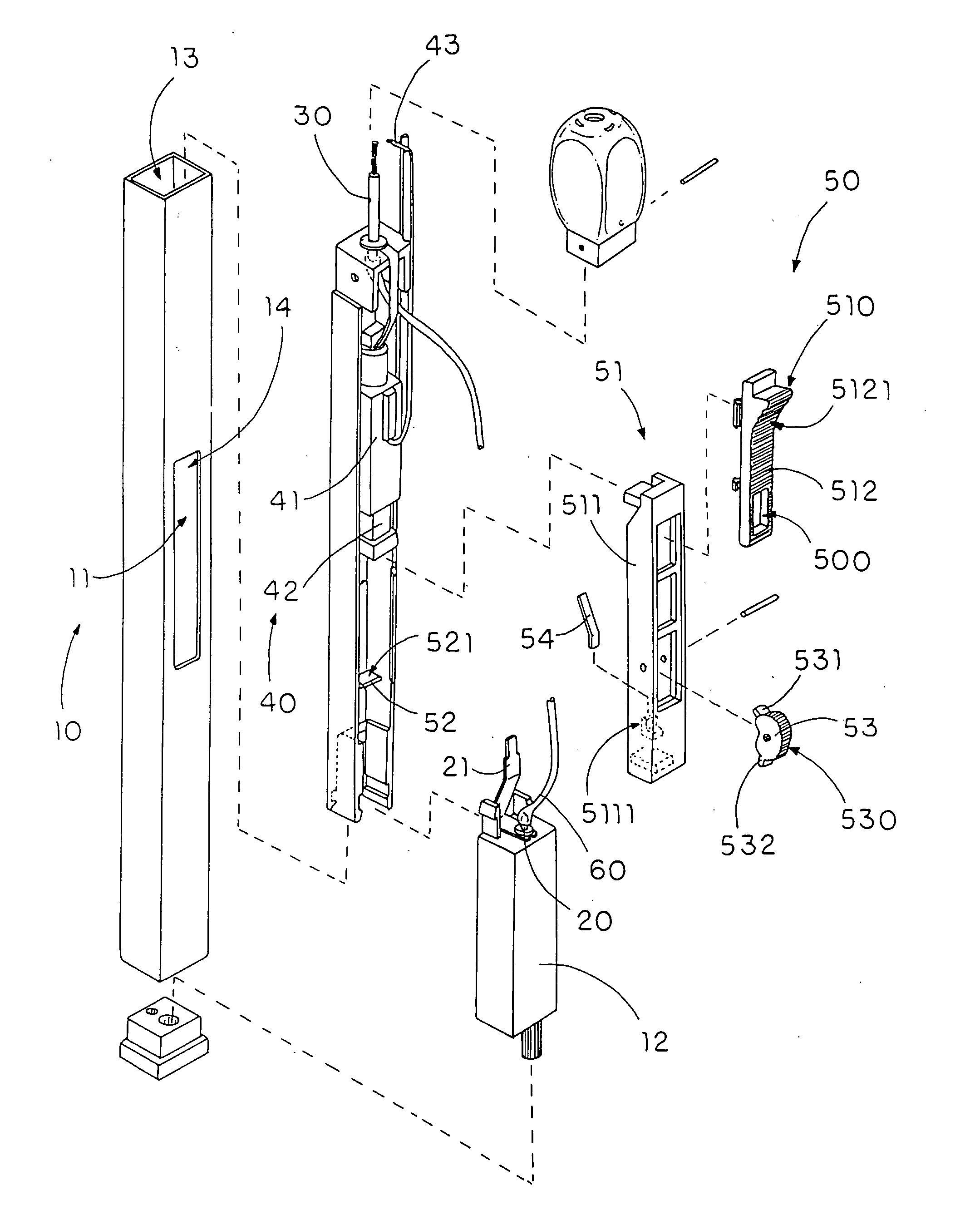
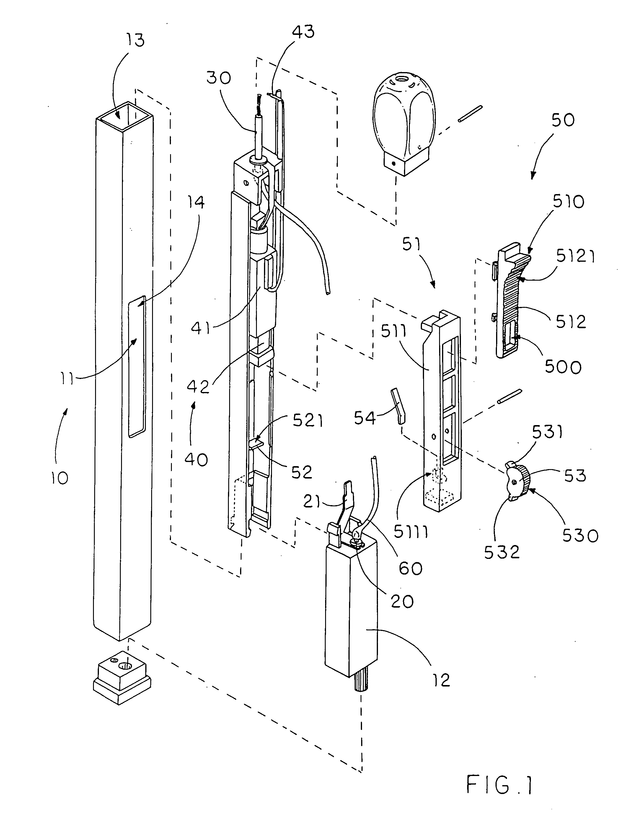
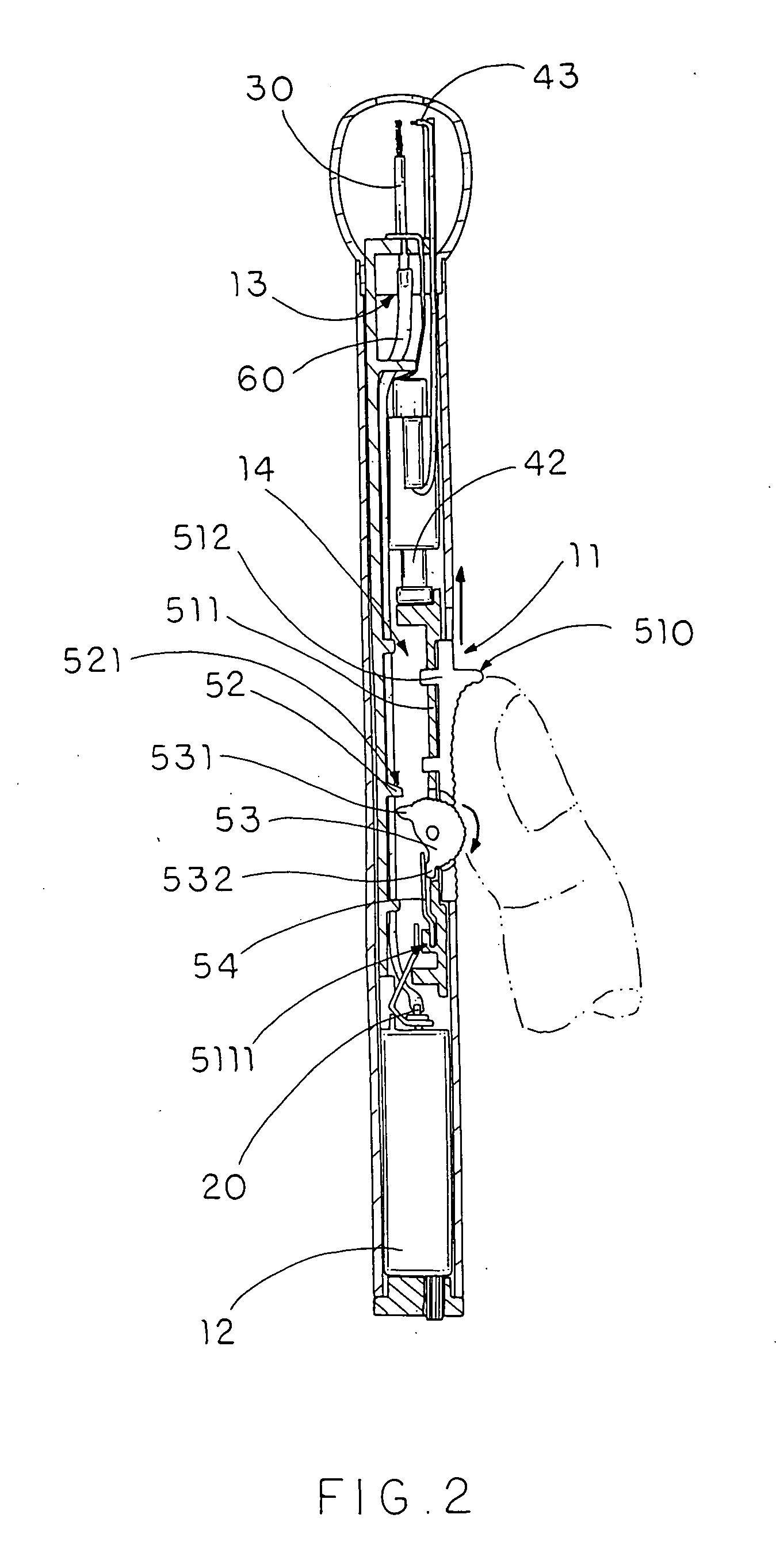
[0062] Referring to FIG. 5 of the drawings, the utility lighter according to a second embodiment illustrates an alternative mode of the first embodiment of the present invention, wherein the utility lighter according to the second embodiment is embodied as a piezoelectric lighter.

[0063] The utility lighter comprises a lighter housing 10′, a gas valve 20′, an ignition nozzle 30′, a piezoelectric unit 40′, and a safety device 50′. The lighter housing 10′ has a fuel-storage cavity 12′ for storing liquefied gas therein, an ignition cavity 13′, and an operation cavity 14′, wherein an operation slot 11′ is formed on the lighter housing 10′ so as to communicate the operation cavity 14′ with an outside of the lighter housing 10′.

[0064] The gas valve 20′ is upwardly extended from the fuel-storage cavity 12′ in such a manner that when it is uplifted, the liquefied gas stored in the fuel-storage cavity 12′ will be released through the gas valve 20′.

[0065] The ignition nozzle 30′ is securely...


PUM


Abstract

A safety device for a utility lighter includes a pusher button slidably mounted on a lighter housing for simultaneously lifting up the gas valve and compressing the piezoelectric unit, a restraining latch transversely extended in the lighter housing, and a safety rotor, which is rotatably connected to the pusher button, having a blocking latch to normally align with the restraining latch to block the upwardly movement of the pusher button for ignition. To ignite the lighter, an adult's thumb has to downwardly rotate the safety rotor to offset the blocking latch with the restraining latch and upwardly push the pusher button in one sequential manner.

Description

BACKGROUND OF THE PRESENT INVENTION [0001] 1. Field of Invention [0002] The present invention relates to a lighter, and more particularly to a utility lighter with a safety device which defines a safety distance through which a thumb of a user's hand has to be traveled for triggering the utility lighter. [0003] 2. Description of Related Arts [0004] A conventional utility lighter usually comprises a lighter case, a fuel-storage chamber having a gas release nozzle provided n the lighter case for storing liquefied gaseous fuel and releasing the gaseous fuel when the has release nozzle is uplifted, a piezoelectric unit, and an ignition triggering device. [0005] The piezoelectric unit comprises a fixed part and a movable part movably attached thereto wherein when the movable element is depressed with respect to the fixed element, a piezoelectric spark will be generated for ignition. [0006] The ignition triggering device comprises a trigger button slidably mounted on the lighter case and ...

Claims


Application Information

Patent Timeline
IPC IPC(8): F23D11/36F23Q7/12
CPCF23Q3/002F23Q2/164
Inventor WONG, CHI LAM
Owner WONG CHI LAM
Why Eureka
Try Eureka