Apparatus and Methods for Sanitizing Fluids in a Chamber

Inactive Publication Date: 2014-09-18
GEA FARM TECH
View PDF2 Cites 0 Cited by
  • Summary
  • Abstract
  • Description
  • Claims
  • Application Information

AI Technical Summary

Benefits of technology

[0013]The sanitizing light can be activated (turned on) by any suitable means such as a switch. The switch can be turned on either manually or automatically, and the switch can be mounted on or otherwise activated by a device associated with the fluid flow diverting lens. For example, a pump used to cause fluid to flow past the flow diverting lens can be activated by a switch or controller that also activates (or turns on) the sanitizing light source. A v

Problems solved by technology

Bacteria growth in fluids is an ongoing problem.
Particularly, milk in dai

Method used


Image

  • Apparatus and Methods for Sanitizing Fluids in a Chamber
  • Apparatus and Methods for Sanitizing Fluids in a Chamber
  • Apparatus and Methods for Sanitizing Fluids in a Chamber

Examples


Embodiment Construction

[0032]In the following detailed description of drawings, the same reference numeral will be used to identify the same or similar parts in each of the figures, unless otherwise noted.

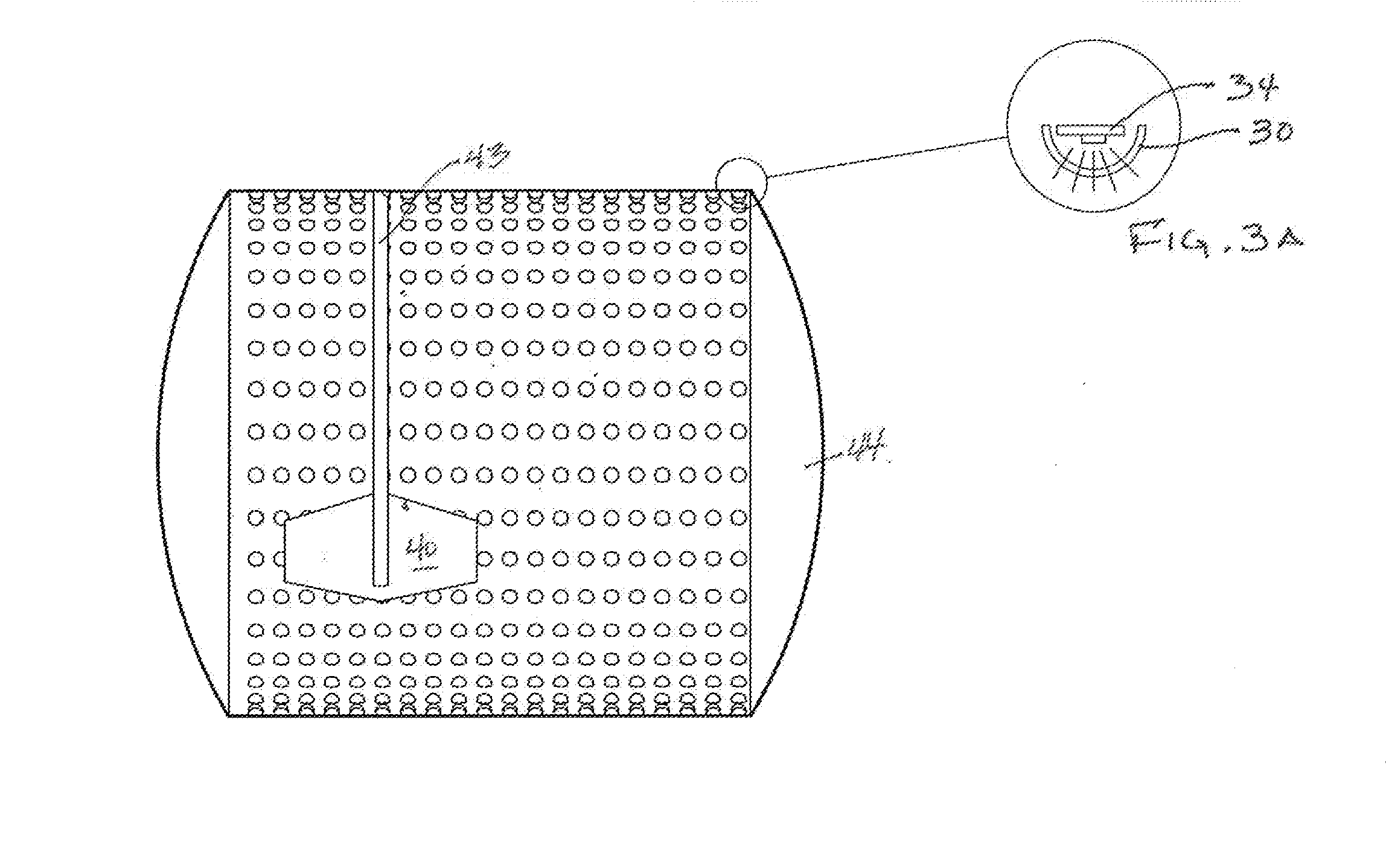
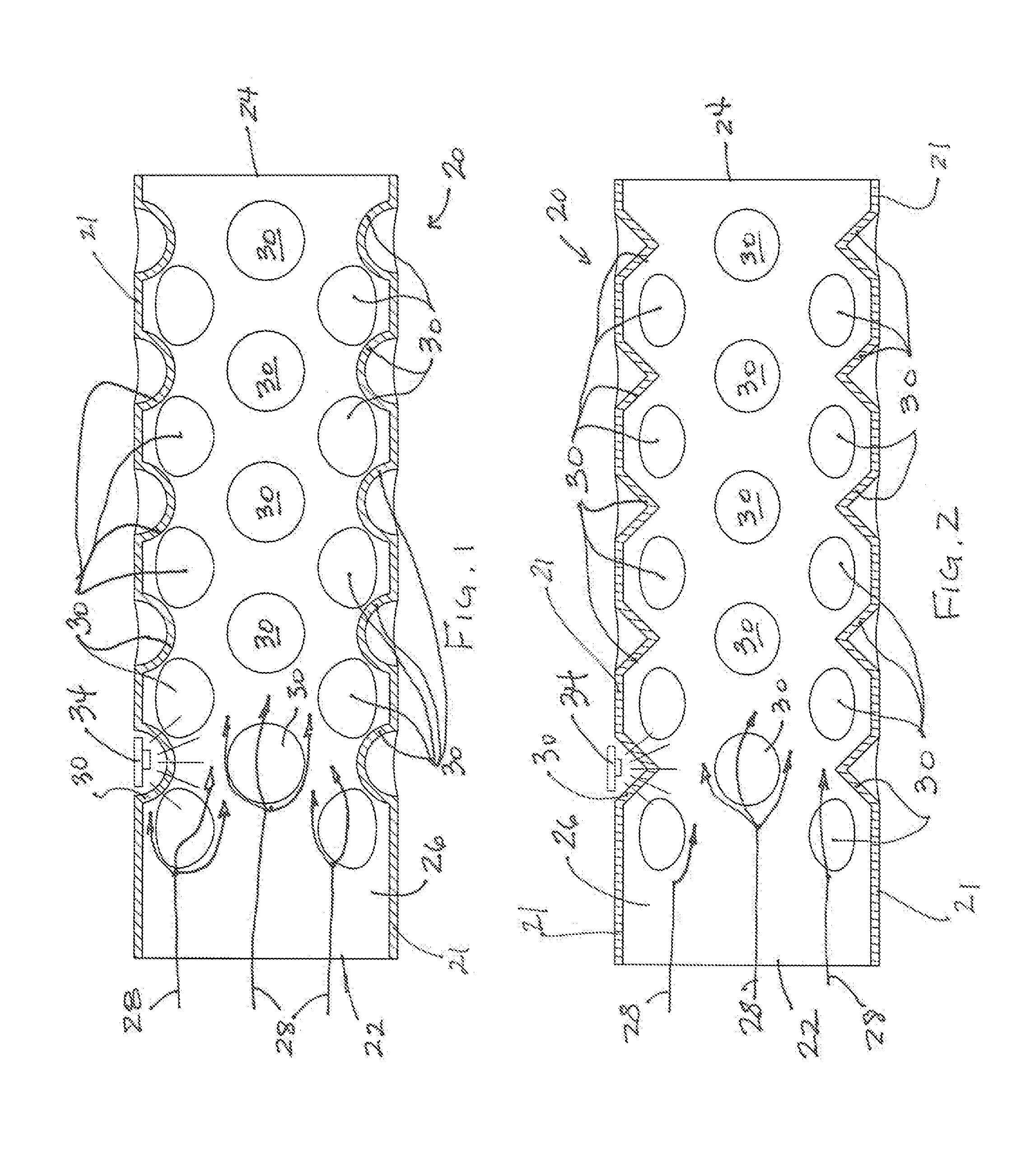
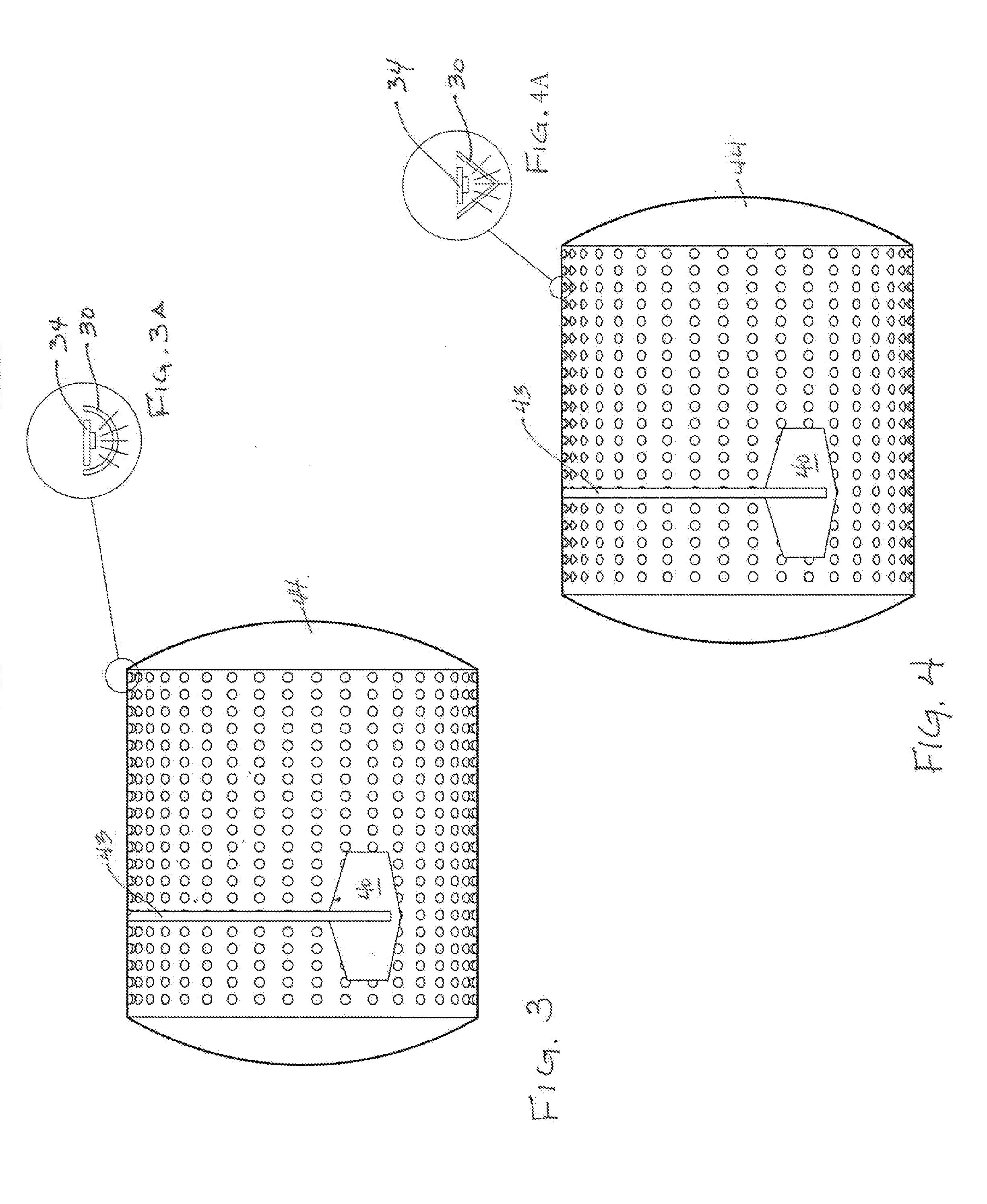
[0033]Depicted in FIGS. 1 and 2 are cross-sections of a milk treatment turbulator 20 having a wall 21, an upstream end 22, a downstream end 24, and a bore 26 through which milk or other dairy fluid flows for treatment to kill or reduce bacteria in the dairy fluid. The dairy fluid is represented by flow lines 28.

[0034]The fluid flow lines 28 illustrate a generally straight flow path through the turbulator inlet 22, and then diverge in a number of directions as they contact flow diverting lenses 30, of which they are preferably a sufficient number to turbulate the dairy fluid for adequate exposure to sanitizing light, as explained below. The fluid flow lines 28 are provided as a visual aid to understanding the effect of the flow diverting lenses 30, but they are not intended to show exact flow patterns or ...


PUM


Abstract

A flow diverting lens through which sanitizing light is transmitted. The flow diverting lens alters fluid flow to enhance fluid exposure to the sanitizing light.

Description

BACKGROUND OF THE INVENTION[0001]This invention relates generally to apparatus and methods for using light to sanitize fluids, and more particularly to flow diverting lenses for improving fluid exposure to the sanitizing light.[0002]Bacteria growth in fluids is an ongoing problem. Particularly, milk in dairy harvesting and processing facilities is vulnerable to bacteria growth. The division of one bacterium into two daughter cells in a process called binary fission and results in an exponential growth of the bacteria over time. Bacteria growth can continue at a constant rate, so both the number of cells and the rate of population increase doubles with each consecutive time period. Spatially structured environments, such as biofilms or bacterial mats, present additional growth foundations. Biofilms, for example, can range from few micrometers in depth to half a meter in depth and contain multiple species. Bacteria protected within biofilms are much harder to kill then individual isol...

Claims


Application Information

Patent Timeline
IPC IPC(8): A61L2/00
CPCA61L2/0047A23C3/076A23L3/26A23L3/28C02F1/325C02F2201/328C02F2301/024
Inventor BECKER, DAVID A.DALEY, SEAN W.
Owner GEA FARM TECH
Why Eureka
Try Eureka