Freeze dryer

a dryer and dryer technology, applied in the direction of dryers with progressive movements, wing accessories, lighting and heating apparatus, etc., can solve the problems of increasing the cost and duration of cleaning and sterilization

Active Publication Date: 2005-09-15
IMA LIFE SRL
View PDF9 Cites 2 Cited by
  • Summary
  • Abstract
  • Description
  • Claims
  • Application Information

AI Technical Summary

Benefits of technology

[0008] The rotating means may be arranged to rotate the door during movement thereof from a closed position, so that the door is gradually rotated as the slot is opened. Alternatively, in a preferred arrangement the moving means is arranged to move the door from the closed position to a second open position at which the cam engages the guide, the slo

Problems solved by technology

In order to access the rear surface of the slot door, that is, the surface of the slot door which faces the chamber, it is necessary

Method used


Image

  • Freeze dryer
  • Freeze dryer
  • Freeze dryer

Examples


Embodiment Construction

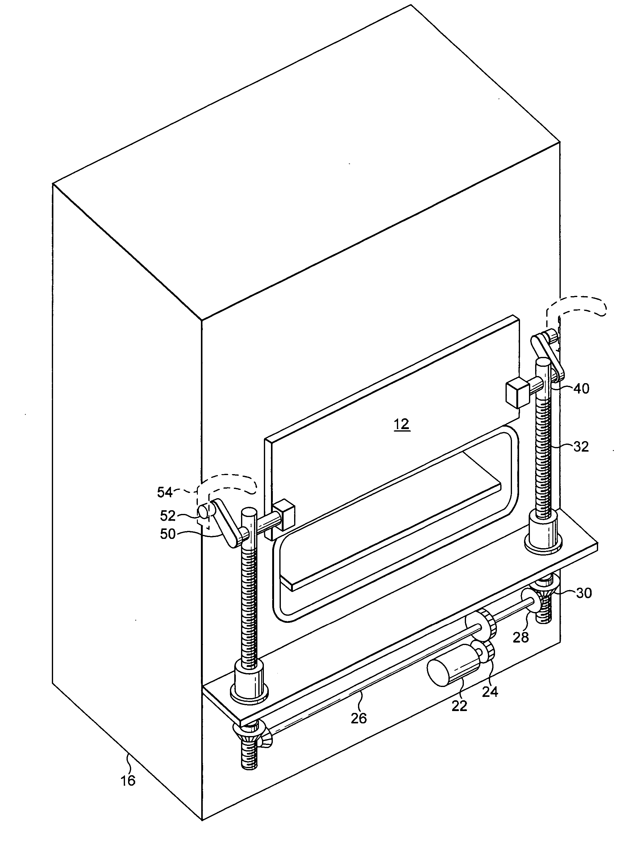
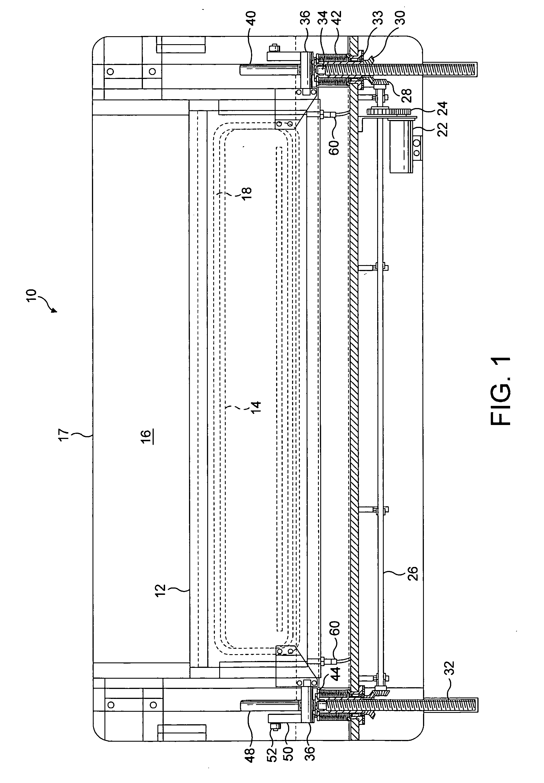
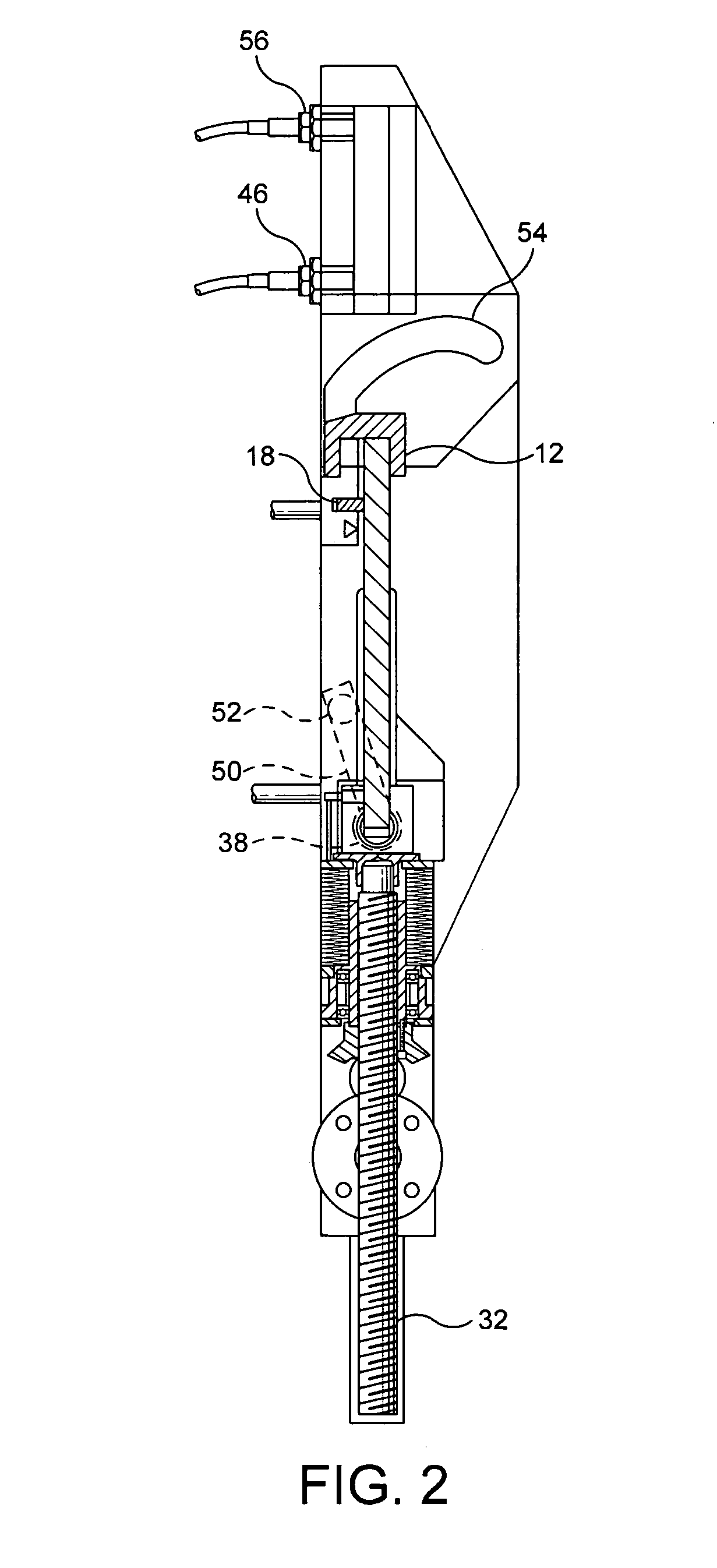
[0022] With reference to FIGS. 1 and 2, an embodiment of a slot door assembly 10 comprises a rectangular slot door 12 for closing a slot 14 formed in a wall or main door of a chamber 16 of a freeze dryer 17 or the like. FIGS. 1, 2 and 5 illustrate the door 12 in a closed position, in which the door 12 engages a sealing arrangement 18 extending around the slot 14 to form a vacuum seal.

[0023] The assembly 10 includes a moving mechanism 20 for raising the door to enable containers or vials to be inserted into and removed from the chamber 16 through the slot 14. The moving mechanism 20 comprises an AC / DC drive motor 22 connected by a timing belt or gear assembly 24 to a drive shaft 26. Gear wheels 28 attached to the ends of the drive shaft 26 intermesh with gear wheels 30 each located on a respective lead screw 32, the lead screws 32 being provided on respective sides of the assembly 10 and supported by bearings 33. Each lead screw 32 may be a normal thread lead screw or a ball screw s...


PUM


Abstract

A freeze dryer comprising a chamber having a rectangular slot through which vials are inserted into the chamber, and a slot door for forming a seal with the chamber to close the slot. To enable the vials to be subsequently removed from the chamber, the slot door is raised. As the door is raised, it is rotated to expose the rear surface of the door for cleaning purposes.

Description

FIELD OF THE INVENTION [0001] The present invention relates to freeze dryers and the like, and more particularly to enclosures for freeze dryers. BACKGROUND OF THE INVENTION [0002] Freeze dryers typically incorporate a pressure vessel having a freeze drying chamber for receiving a plurality of containers or vials containing sterile material to be freeze dried. Access to the chamber for automated loading and removal of vials is through a rectangular opening, or slot, formed in a wall or in the main door of the chamber. The slot is closed by a slot door which, with the chamber, forms a vacuum seal around the slot. To enable vials to be inserted into and removed from the chamber, the slot door is vertically raised relative to the slot by moving the slot door along guide tracks. [0003] Maintaining sterile conditions within the dryer requires periodic cleaning and sterilization of the slot door and guide tracks. In order to access the rear surface of the slot door, that is, the surface o...

Claims


Application Information

Patent Timeline
IPC IPC(8): E05D15/58F26B5/06F26B25/12
CPCF26B5/06F26B25/12
Inventor DAMEN, FRANSDEMARCO, FRANCIS W.RENZI, ERNESTO
Owner IMA LIFE SRL
Why Eureka
Try Eureka