Powder formation by atmospheric spray-freeze drying

a technology of atmospheric spray-freeze drying and powder, which is applied in the direction of drying solid materials without heat, drying machines with progressive movements, lighting and heating apparatus, etc. it can solve the problems of unstable pharmaceutical compounds, uneconomical process, and easy damage to pharmaceuticals, so as to maintain drug bioactivity, reduce the effect of economic cost and high emitted dos

Active Publication Date: 2006-03-07
AEROSOL THERAPEUTICS
View PDF10 Cites 72 Cited by
  • Summary
  • Abstract
  • Description
  • Claims
  • Application Information

AI Technical Summary

Benefits of technology

[0006]It is therefore an object of this invention to provide atmospheric spray freeze drying of liquid carrying pharmaceuticals to produce a powder by a pharmaceutical powder process that maintains drug bioactivity at low economic cost. The invention provides a method of manufacturing a powder or particulate pharmaceutical substance, and an apparatus for carrying out the method. The powder produced by this process is believed to exhibit higher emitted dose and better preservation of bioactivity than spray-dried particles and milled particles. In addition, the porous nature of the particles provides rapid dissolution properties. The invention is applicable to the formation of other powders, including powder forms of nutraceuticals and foods.

Problems solved by technology

Pharmaceuticals are often unstable compounds that degrade rapidly during processes that lead to a powder form of the pharmaceutical.
Since the pharmaceutical compound is usually carried in an aqueous solution, and the aqueous solution must be dried to form the powder, the required desiccation or drying process may easily damage the pharmaceutical.
At the same time, if the process of forming the powder takes too long, or is too energy consuming, the process may become uneconomic.
The temperature (<<0° C.) and the maintenance of the frozen state lead to very low driving forces for heat and mass transfer and therefore, often to very low drying rates and very long drying times. Thus, despite its capability of providing a very high-quality dehydrated product, freeze-drying has been and remains highly energy-intensive and consequently, is a very expensive dehydration process.
Despite the potential advantages of atmospheric lyophilization, the challenge still remains to provide a combination of spray-freezing solution / suspension into liquid and atmospheric freeze-drying that meets industrial demands for a pharmaceutical powder process that maintains drug bioactivity at low economic cost.

Method used


Image

  • Powder formation by atmospheric spray-freeze drying
  • Powder formation by atmospheric spray-freeze drying
  • Powder formation by atmospheric spray-freeze drying

Examples


first embodiment

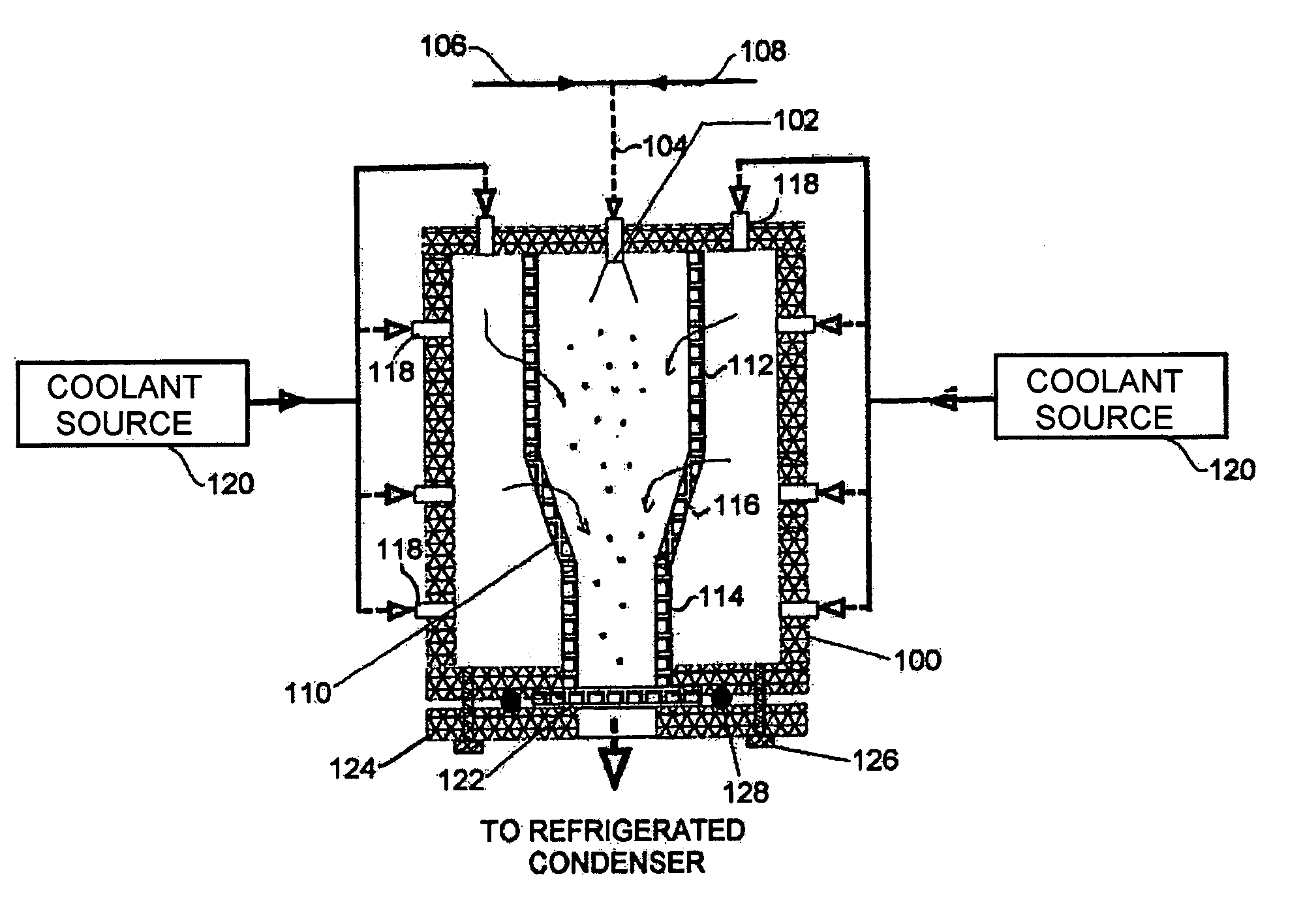
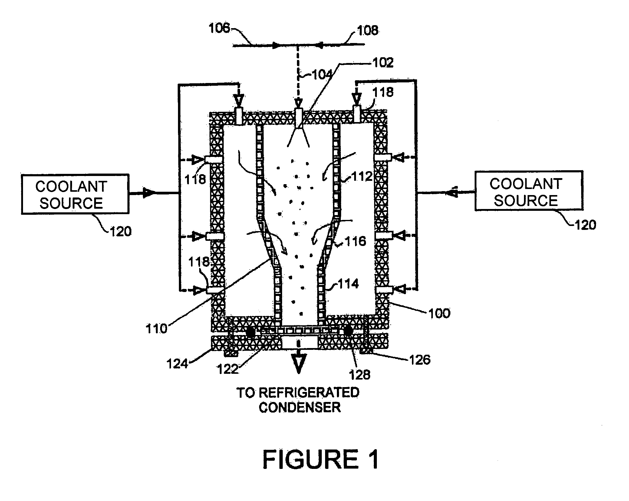
[0018]Referring to the first embodiment shown in FIG. 1, a housing 100 formed with solid insulated walls supports at an inlet end an atomizer 102 that is supplied through line 104 with compressed gas from source 106 and a suitable carrier liquid from source 108. Inside the housing 100 is a flow chamber 110 with porous walls. The flow chamber 110 is formed of cylindrical sections 112, 114 of differing diameter joined by a conical section 116. Multiple nozzles 118 of a nozzle system penetrate the housing 100 and supply a cryogenic flow of coolant from a coolant source 120 into the space between the housing 100 and flow chamber 110. At the other, exit, end of the housing 100 from the atomizer 102, the flow chamber 110 terminates in a filter 122 that is held across an opening in the housing 100 by a plate 124 fixed to the chamber 100 by bolts or clamps 126 with O-ring 128. Gas flow from the exit end of the housing 100 is returned to a refrigerated condenser that forms part of the coolan...

second embodiment

[0019]Referring to a second embodiment shown in FIG. 2, a housing 200 formed with solid insulated walls supports at an inlet end an atomizer 202 that is supplied through line 204 with compressed gas from source 206 and a suitable carrier liquid from source 208. Inside the housing 200 is a flow chamber 210 defined by solid walls lining the housing 200. The flow chamber 210 is formed of cylindrical sections 212, 214 of differing diameter joined by a conical section 216. Surrounding the atomizer 202 is a nozzle system in the form of a ring nozzle 218, with openings 219 directing flow from the ring nozzle 218 parallel to flow from the atomizer 202. The ring nozzle 218 supplies a cryogenic flow of coolant from a coolant source 220, for example a liquid nitrogen cylinder driven by compressed gas that surrounds flow from the atomizer 202 in the spray-freezing step and a refrigerated condenser in the following drying step. At the other, exit, end of the housing 200 from the atomizer 202, th...

third embodiment

[0020]Referring to a third embodiment shown in FIG. 3, a housing 300 formed with solid insulated walls supports at an inlet end an atomizer 302 that is supplied through line 304 with compressed gas from source 306 and a suitable carrier liquid from source 308. Inside the housing 300 is a cylindrical flow chamber 310 defined by solid walls lining the housing 300. Surrounding the atomizer 302 is a ring nozzle 318, with openings 319 directing flow from the ring nozzle 318 parallel to flow from the atomizer 302. The ring nozzle 318 supplies a cryogenic flow of coolant from a coolant source 320, for example a liquid nitrogen cylinder driven by compressed gas that surrounds flow from the atomizer 302 in the spray-freezing step and a refrigerated condenser in the following drying step. At the other, exit, end of the housing 300 from the atomizer 302, the flow chamber 310 terminates in a filter 322 that is held across an opening in the housing 300 by a plate 324 fixed to flanges 325 on the ...


PUM


Abstract

A method of manufacturing heat-sensitive pharmaceutical powder is disclosed. The original pharmaceutical substances are dissolved in a solution or suspended in a suspension, which is sprayed through an atomizing nozzle and frozen in a cold gas phase or liquid nitrogen atomized directly in the spray-freeze chamber or gas jacket at the same time (for cooling purposes). The particles are freeze-dried at roughly atmospheric pressure in a down-stream fluid flow with exit filter thereby to remove moisture entrapped on or inside the frozen particles. The system has applicability for forming other powders.

Description

BACKGROUND OF THE INVENTION[0001]This invention relates to the preparation of powders, particularly for the administration of pharmaceuticals to humans.[0002]Pharmaceuticals are often unstable compounds that degrade rapidly during processes that lead to a powder form of the pharmaceutical. Since the pharmaceutical compound is usually carried in an aqueous solution, and the aqueous solution must be dried to form the powder, the required desiccation or drying process may easily damage the pharmaceutical. At the same time, if the process of forming the powder takes too long, or is too energy consuming, the process may become uneconomic.[0003]Freeze drying (lyophilization), which has conventionally been used to prepare pharmaceutical powders, provides a two step preservation and dehydration process in which the product is first frozen and the water is then removed as vapor from the frozen state. As the water passes from the solid phase directly into the vapor phase, it is necessary that...

Claims


Application Information

Patent Timeline
Patent Type & Authority Patents(United States)
IPC IPC(8): F26B5/06F26B13/30
CPCF26B13/30F26B5/06F26B5/065B01J2/04B01D1/18F26B3/12
Inventor WANG, ZHAOLINFINLAY, WARREN H.
Owner AEROSOL THERAPEUTICS
Why Eureka
Try Eureka