Method and apparatus for movable structure having alternative accessible sides

a technology of accessible side and movable structure, which is applied in the field of storage structures, can solve the problems of space loss, waste of space, and loss of space in the front of the cabinet, and achieve the effects of improving rotational storage, saving space, and saving spa

Inactive Publication Date: 2005-09-15
STONE WILLIAM JEFFERSON III
View PDF17 Cites 18 Cited by
  • Summary
  • Abstract
  • Description
  • Claims
  • Application Information

AI Technical Summary

Benefits of technology

[0018] In view of the above-stated disadvantages of the prior art, objectives of the invention include providing an improved rotational storage for applications where alternative access to different sides of the cabinet is practical or needed.
[0019] Another objective of the invention is to provide a storage cabinet that is economical in utilizing the space allocated for it. In addition to being economical in utilizing the space around the storage cabinet, its design should provide access to different sides of the cabinet with convenience and ease.
[0020] A further objective of the invention is to provide limited access to the side or sides of the cabinet that are not being accessed at a given time. This secure access should be achieved economically and with simplicity of design.
[0021] A still further objective of the invention is to provide a storage cabinet that can be utilized for applications with heavy loads such as for example storing books, firearms, electronic equipment, and the like.
[0022] Another objective of the invention is to provide a storage cabinet that can be simple in design with low cost for light load applications such as for example CDs, DVDs, stamp collections, and the like.

Problems solved by technology

There are disadvantages associated with these conventional designs.
For example, the first disadvantage is loss of space because these conventional designs require significant space around the rotating object so that it can perform a rotation around an axis.
Space loss in the front of the cabinet can typically be seen as a temporary loss because the space is lost only when the cabinet is rotating.
The space loss, however, is more wasteful when space is lost behind the cabinet.
Space loss behind a cabinet is typically considered a permanent loss of space because such space has no practical utilization.
A drawback associated with this design is space loss in front of the cabinet.
This type of space loss can become a serious problem if space is at premium.
A second disadvantage associated with some conventional designs is lack of exclusive access.
Conventional designs do not typically offer exclusive accessibility to one side of the storage cabinet while other sides of the cabinet are not accessible.
This is not suitable when alternative access to different sides is needed.
However, providing special enclosures and / or shields as solutions are typically impractical in terms of convenience or cost, e.g., when storage cabinet is used for relatively large articles (books, TV sets, etc.).
A problem associated with the above-referenced designs is safety.
For example, if the weight of stored articles in a cabinet is greater then the weight of the cabinet itself, the loaded cabinet can become heavy and cumbersome to rotate and may also create safety issues because it could tip over if it is not supported from the top.
However, providing support from the top may increase the complexity and bulkiness of such designs and may also increase the total cost of the storage cabinet.
As mentioned, one problem in these conventional designs is waste of space.
In the case of a bookcase in which the bookcase has two storage sides for accessing stored articles waste of space is significant in conventional rotating designs.
Even though the cam system reduces the problem of space waste, it generates new problems.
For example, a problem associate with the cam system is uneven loading of the cabinet weight.
This multi-functionality of the central bottom cam follower lowers the reliability and lifetime of the cabinet.
Another problem associated with the cam system of Schill is that upper and lower cam followers move independently of each other in the guides.
There is no guarantee that these guides will move synchronously.
First, uneven weight distribution of the cabinet articles inside the cabinet; and second, uneven pull or push of the shelf by the person rotating the shelf.
Independent movement of the cam followers may cause the cam followers to be jammed in the guides.
Even if there is no jam there is a high degree of wear and tear in the guiding system, which shortens the lifetime of the cabinet.
The conventional design using a cam system with an upper guiding system to support the cabinet in addition to the bottom guiding system, as described in U.S. Pat. No. 4,124,262, adds an undesirable complication of the shelf design when the cabinet is used for light loads and top support is not needed.
Another problem with the design of the cam system is that it is dimension dependent.
This adds serious complications in the cabinet design by requiring dynamic elongations to the guiding grooves of the enclosure with telescoping guides.
Also, for heavy loaded cabinets that are not deep but wide, it is especially impractical for reliability and safety concerns.

Method used


Image

  • Method and apparatus for movable structure having alternative accessible sides
  • Method and apparatus for movable structure having alternative accessible sides
  • Method and apparatus for movable structure having alternative accessible sides

Examples


Embodiment Construction

[0043] In the following description, for purposes of explanation, numerous specific details are set forth to provide a thorough understanding of the present invention. It will be apparent, however, to one skilled in the art that these specific details may not be required to practice the present invention.

[0044] In the following description of the embodiments, substantially the same parts are denoted by the same reference numerals. Also, while references such as top, bottom and side may be used throughout the specification, it is to be understood that their orientation requirements are only to facilitate the explanation of the various embodiments and depending on the application, the top could be the side or bottom or vice versa.

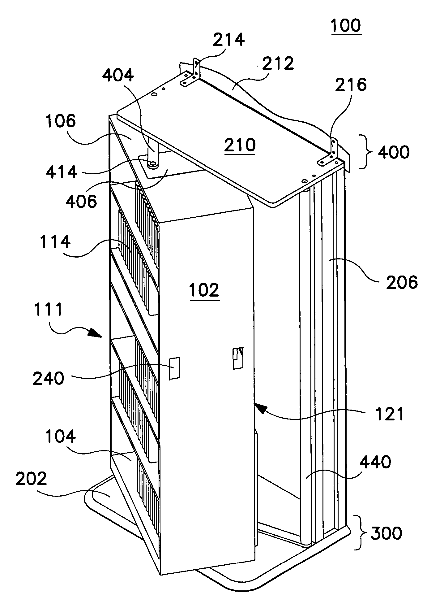
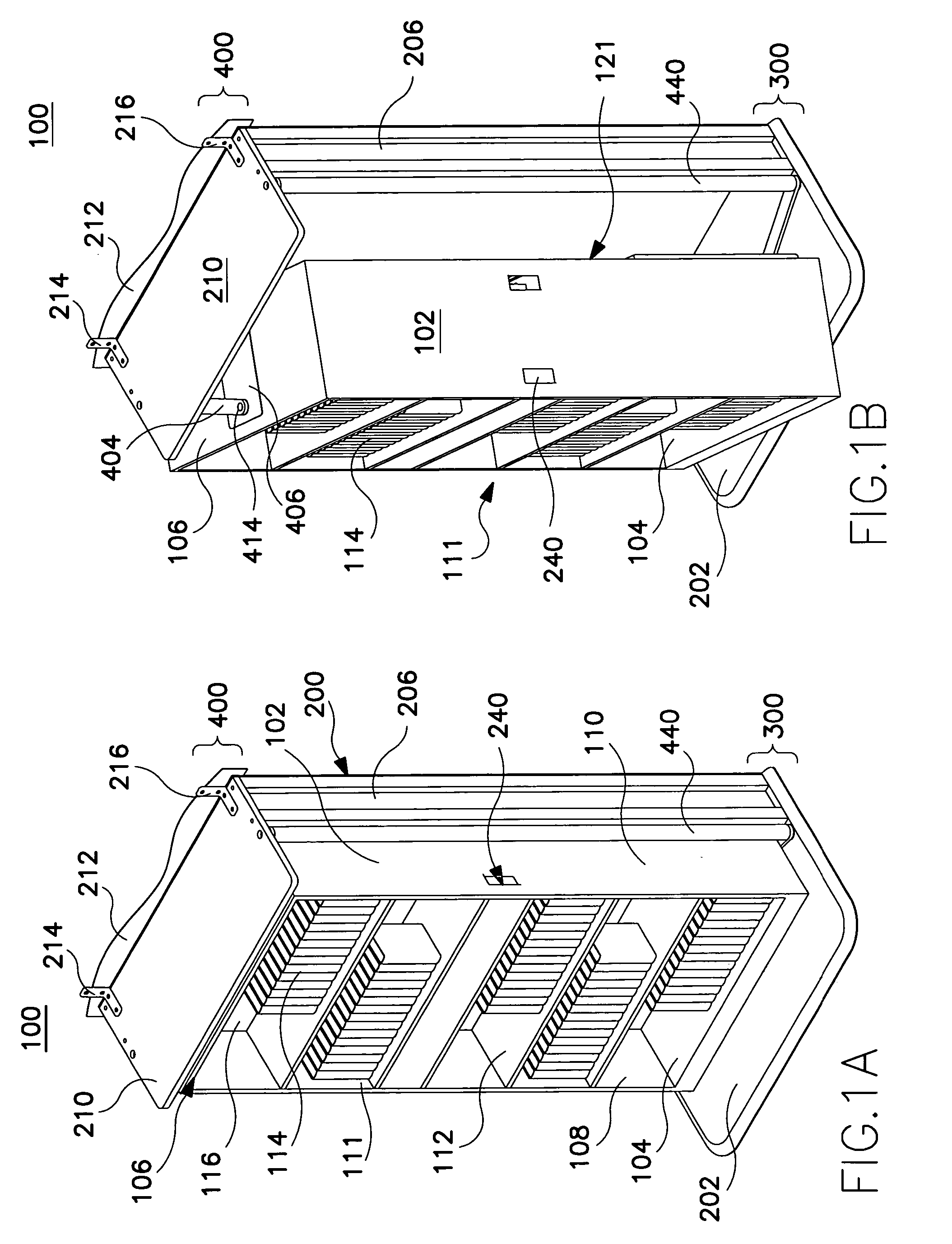
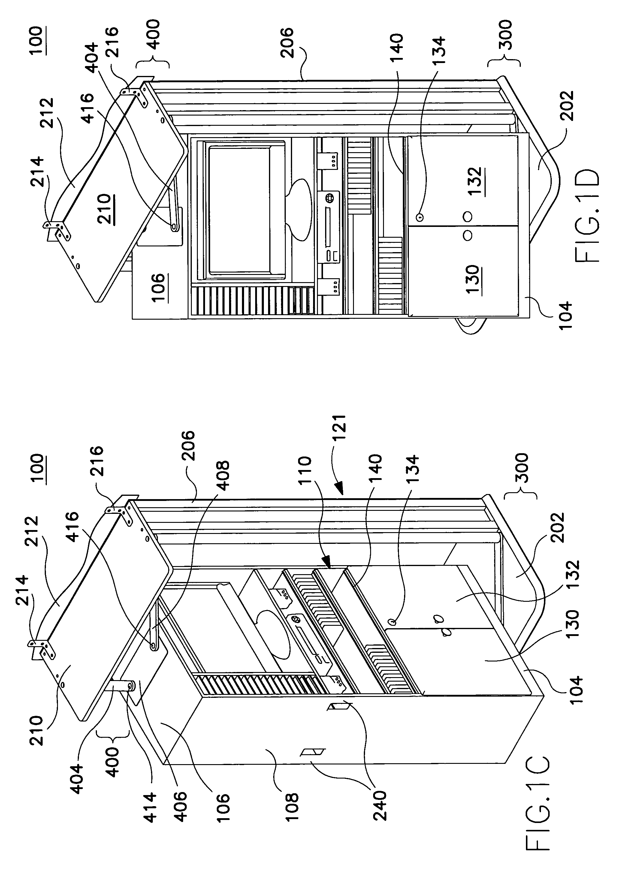
[0045] An apparatus for a reversible storage system having a moving object 102 is disclosed in the present application. The reversible storage system, in one embodiment, includes an object 102 and a frame 200. A first side of frame is situated at a substant...


PUM


Abstract

A method and apparatus for a structure having a moving object are disclosed in the present application. The structure, in one embodiment, includes an object and a outside structure. A first side of outside structure is situated at a substantially fixed distance from a second side of outside structure. The structure further includes two links wherein a first end of a first link is coupled to the first side of outside structure and a second end of first link is coupled to the object. Also, a first end of a second link is coupled to the second side of outside structure and a second end of second link is coupled to the object. The object is capable of performing a rotaxial rotation in response to the first and second links.

Description

PRIORITY [0001] The present application is a continuation-in-part of U.S. patent application Ser. No. 10 / 877,530, filed on Jun. 24, 2004, which claims priority to the provisional application Ser. No. 60 / 482,048, filed on Jun. 24, 2003.FIELD OF THE INVENTION [0002] The present invention relates generally to storage structures that are used for supporting, holding and safekeeping objects. More particularly, the present invention relates to a reversing storage cabinet. BACKGROUND [0003] A typical structure, such as a cabinet, furniture, et cetera, may contain rotatable unit(s), for example, a cabinet may have a “lazy Susan” tray. These rotatable units have widespread applications from cabinetry design to sophisticated high precision equipment. There are a number of commercially available designs with regard to rotatable units within a structure on the market. [0004] There are storage cabinets known in the prior art that rotate around an axis. For example, the storage cabinet described ...

Claims


Application Information

Patent Timeline
Patent Type & Authority Applications(United States)
IPC IPC(8): A47B91/00A47B97/00
CPCA47B81/00A47B46/00
Inventor STONE, WILLIAM JEFFERSON III
Owner STONE WILLIAM JEFFERSON III
Why Eureka
Try Eureka