Image display apparatus, drive method for the image display apparatus, and television set

a drive method and image display technology, applied in the direction of cathode ray tubes/electron beam tubes, instruments, electric discharge tubes, etc., can solve the problems of high degree of manufacturing equipment, high degree of process control, and non-uniform characteristics of individual electron emission devices. achieve the effect of high-quality image display

Inactive Publication Date: 2005-09-15
CANON KK
View PDF20 Cites 6 Cited by
  • Summary
  • Abstract
  • Description
  • Claims
  • Application Information

AI Technical Summary

Benefits of technology

[0043] According to the invention, it is possible to provide high-quality image display by correcting and uniformizing the nonuniform

Problems solved by technology

If an image display apparatus is manufactured with the multi-electron source, there occurs the problem that the nonuniformities of the characteristics of the individual electron emission devices appear as rough feeling (nonuniformity) of luminance.
The reason why the electron emission characteristics of the multi-electron source differ among the individual electron sources is considered to be due to various causes such as the nonuniformity of ingredients of a material used for the electron emission section and the error of the dimension and shape of each member of the electron emission devices.
However, if all these causes are to be eliminated, a very high degree of manufacturing equipment and very strict process control become necessary, but it is not realistic to satisfy all these demands, because huge manufacturing costs occur.
However, if the phosphors are used for a large-screen image display apparatus, thickness irregularity may occur in the phosphors within the screen and cause irregularity in the emission efficiency of the same.
This causes deterioration of the luminance uniformity of the screen.
A metal back, which is generally

Method used


Image

  • Image display apparatus, drive method for the image display apparatus, and television set
  • Image display apparatus, drive method for the image display apparatus, and television set
  • Image display apparatus, drive method for the image display apparatus, and television set

Examples


Embodiment Construction

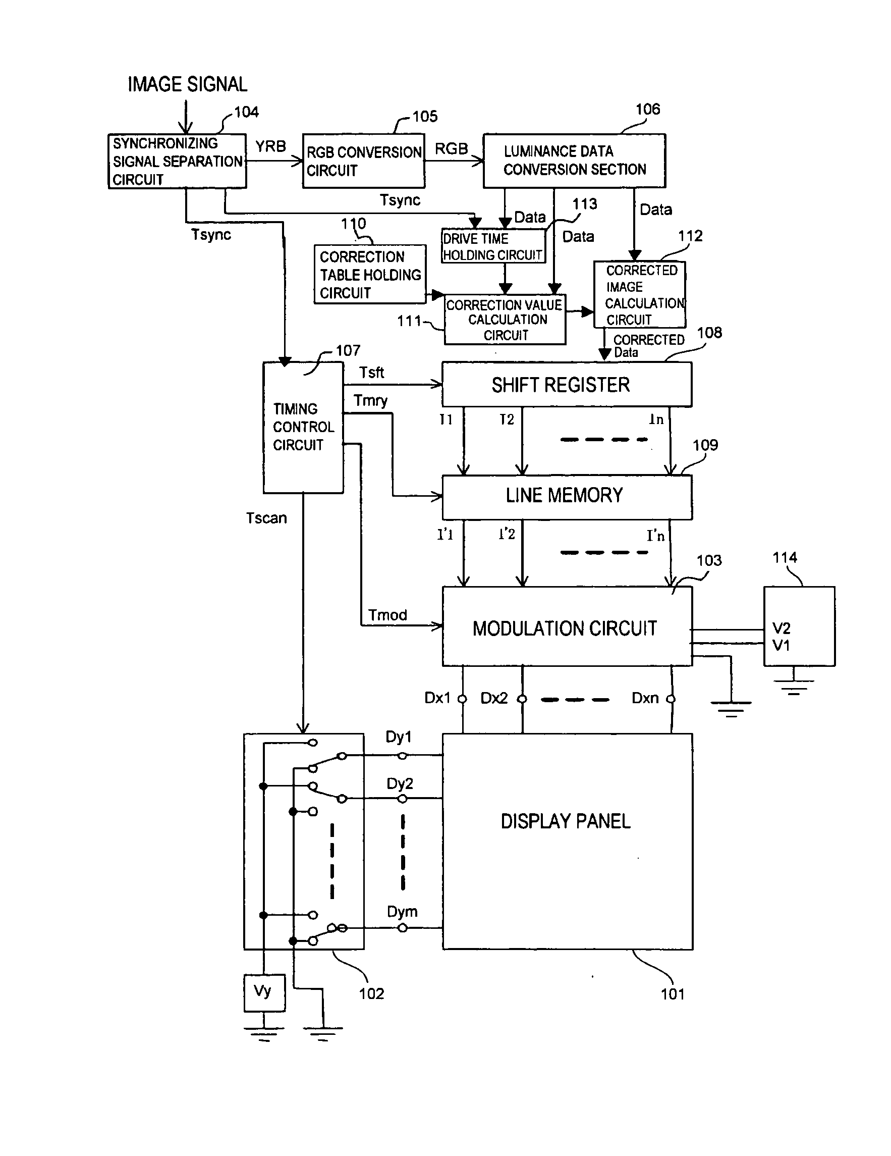
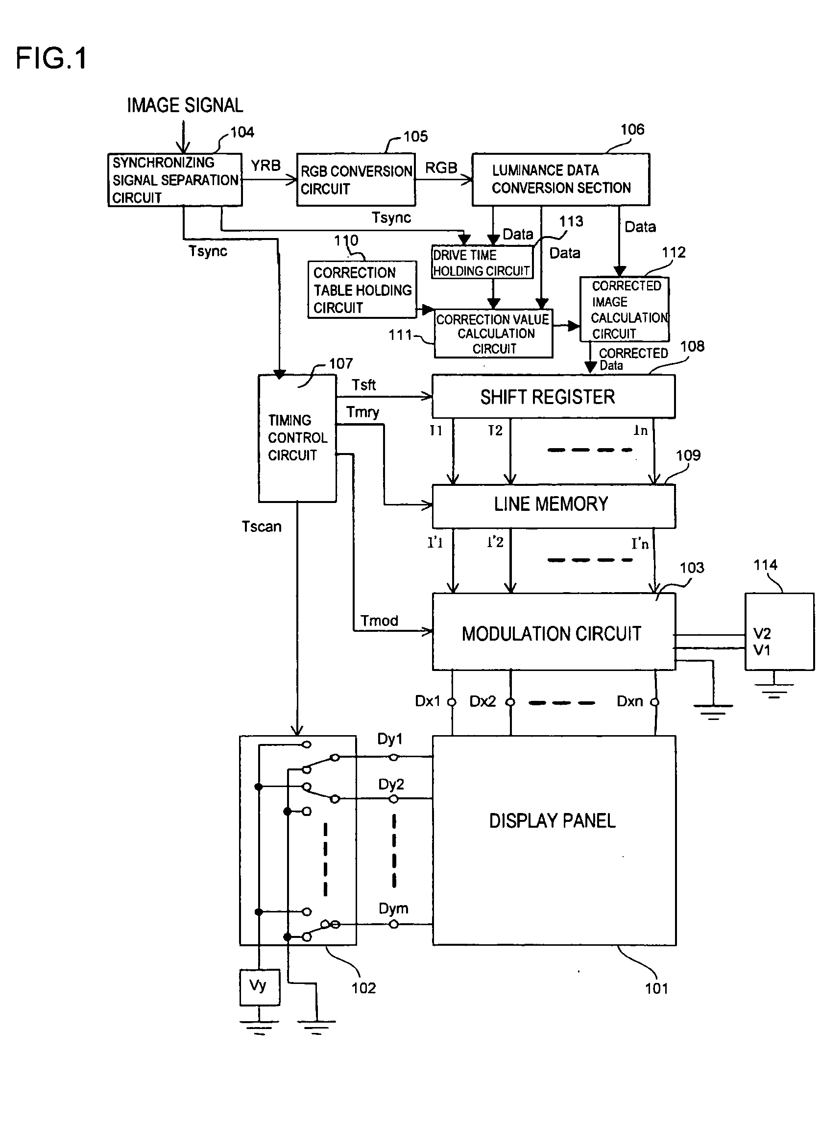
[0053] An image display apparatus according to a preferred embodiment of the invention will be described below with reference to FIG. 1.

[0054]FIG. 1 is a schematic block diagram showing one example of a circuit construction which realizes the image display apparatus according to the preferred embodiment of the invention as well as a driving method for the same.

[0055] (Entire Construction of Image Display Apparatus)

[0056] The image display apparatus shown in FIG. 1 includes a display panel 101 having a plurality of image forming elements arranged in the form of a passive matrix wiring, terminals Dy1 to Dym to which row wirings of the display panel 101 are respective connected, terminals Dx1 to Dxm to which column wirings of the display panel 101 are respectively connected, a scanning circuit 102, a modulation circuit 103, a synchronizing signal separation circuit 104, a RGB conversion circuit 105 which converts to RGB signals YRB signals received from the synchronizing signal sepa...


PUM


Abstract

In order to provide high-quality image display by correcting and uniformizing the nonuniformity of electron emission characteristics, a predetermined arithmetic operation is performed by using correction values for correcting the nonuniformities of luminance caused by the electron emission devices when a predetermined voltage is applied thereto, thereby calculating correction values when the voltage having a plurality of voltage amplitude values is applied thereto. Corrected image data are calculated on the basis of the calculated correction values, and a drive signal is outputted to drive the electron emission devices on the basis of the corrected image data.

Description

BACKGROUND OF THE INVENTION [0001] 1. Field of the Invention [0002] The present invention relates to an image display apparatus, a drive method for the image display apparatus, and a television set and, more particularly, to an image display apparatus having a plurality of electron emission devices and phosphors, a drive method for the image display apparatus, and a television set [0003] 2. Description of the Related Art [0004] As panel types of self-luminous image display apparatuses, there are, for example, displays having pixels in each of which phosphors and microscopic electron emission devices are arranged, displays using electroluminescence, and displays in which a multiplicity of light-emitting diodes are arranged. [0005] As an example which includes as electron emission devices a multiplicity of surface conduction electron emission devices (hereinafter referred to as the SCEs) arranged in a passive matrix form and is applied to an image display apparatus, there are U.S. Pat...

Claims


Application Information

Patent Timeline
IPC IPC(8): G09G1/04G09G3/22G09G3/20G09G3/32
CPCG09G3/22G09G2320/0285G09G2320/0233
Inventor YAMANO, AKIHIKOOGUCHI, TAKAHIRO
Owner CANON KK
Why Eureka
Try Eureka