Polarization element and projector

a technology of polarization element and projector, which is applied in the direction of polarizing element, non-linear optics, instruments, etc., can solve the problems of deteriorating image quality, affecting image quality, and raising manufacturing costs, so as to improve image quality, prevent deterioration of polarization element, and improve image quality

Active Publication Date: 2014-04-15
SEIKO EPSON CORP
View PDF25 Cites 11 Cited by
  • Summary
  • Abstract
  • Description
  • Claims
  • Application Information

AI Technical Summary

Benefits of technology

[0009]An advantage of some aspects of the invention is to provide a polarization element and a projector capable of selectively absorbing unwanted polarized light to thereby be superior in grayscale expression, realize high-quality image display, and further simplify the element structure to achieve cost reduction.

Problems solved by technology

This is because, if the unwanted polarized light is reflected on the light exit side of the light valve, there might arise a problem that the reflected light enters the light valve again to cause temperature rise in transistors, which makes the grayscales out of order, or to become stray light, which degrades the image quality.
However, in Document 1, since deposition of the absorbing layer is required in addition to formation of the polarization element, and therefore, the structure of the element becomes complicated to thereby raise the manufacturing cost.

Method used


Image

  • Polarization element and projector
  • Polarization element and projector
  • Polarization element and projector

Examples


first embodiment

Polarization Element of First Embodiment

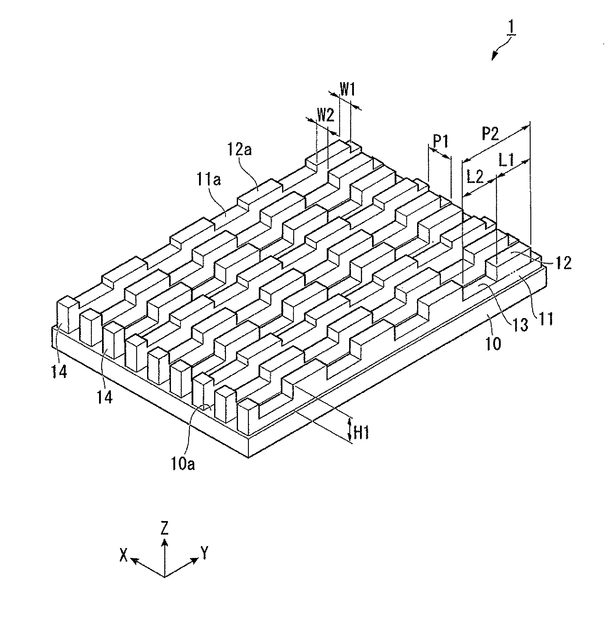
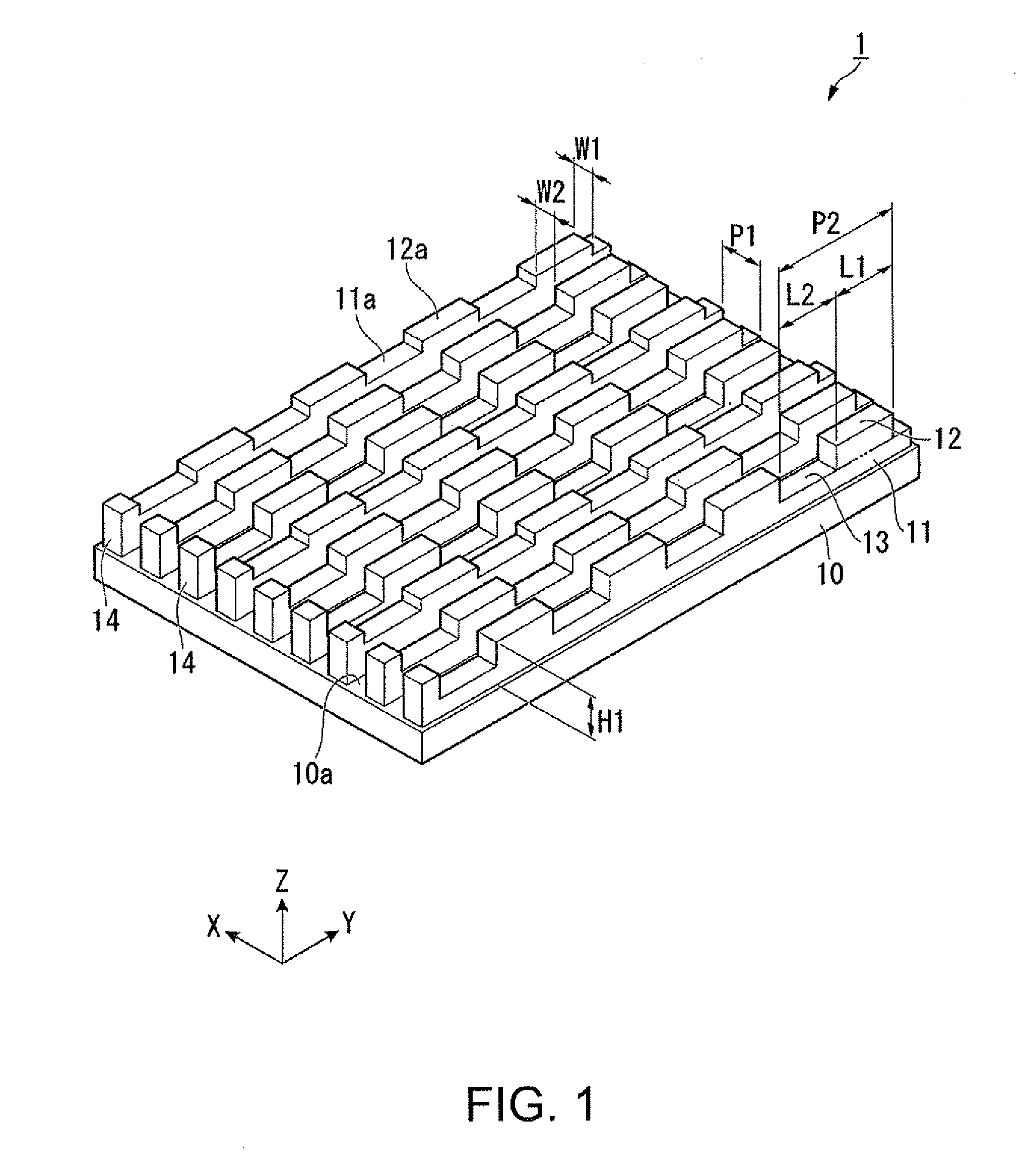
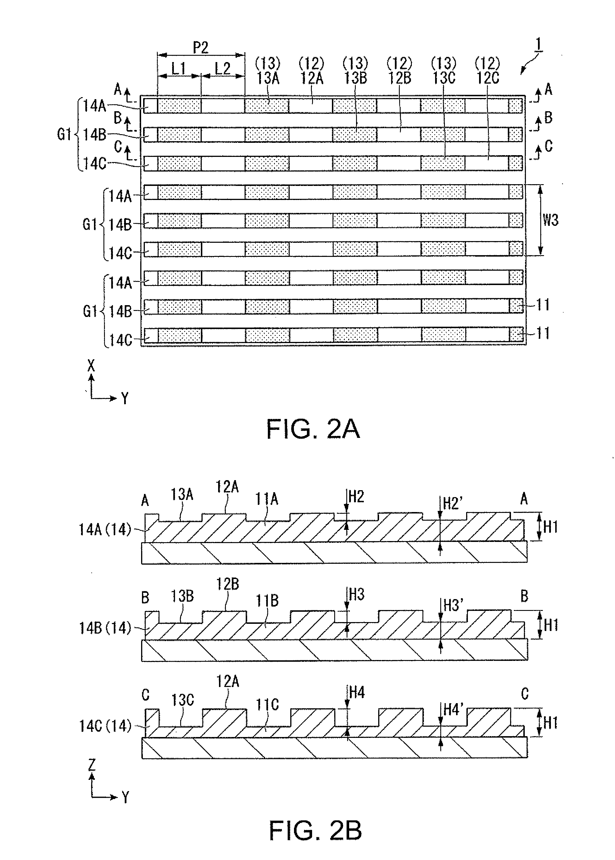
[0046]FIG. 1 is a perspective view showing a schematic configuration of a polarization element according to a first embodiment of the invention. FIG. 2A is a plan view showing a schematic configuration of the polarization element, and FIG. 2B is a partial cross-sectional view showing a schematic configuration of the polarization element.

[0047]In FIG. 1, the reference symbol P1 denotes the pitch of the thin metal wires, the reference symbol P2 denotes the pitch of protruding sections, the reference symbol H1 denotes the height of each of the thin metal wires, and in FIG. 2B the reference symbols H2, H3, and H4 denote the heights of the protruding sections. Further, it is assumed that an extending direction of the thin metal wires is the Y-axis direction, and the arranging axis of the thin metal wires is the X-axis direction.

[0048]As shown in FIGS. 1 and 2B, the polarization element 1 has a structure of absorbing the unwanted polarized light usi...

second embodiment

Polarization Element of Second Embodiment

[0096]Then, the polarization element according to a second embodiment will be described. FIG. 7A is a plan view showing a schematic configuration of the polarization element according to the second embodiment, and FIG. 7B is a partial cross-sectional view showing a schematic configuration of the polarization element according to the second embodiment.

[0097]Although in the embodiment described above there is described the configuration in which the height of the protruding sections is different between the grid sections adjacent to each other, in the present embodiment there is adopted a configuration in which the heights of the protruding sections of the respective grid sections are set to be equal to each other, and the proportion of the protruding sections is different between the grid sections adjacent to each other.

[0098]As shown in FIG. 7A, the polarization element 2 according to the present embodiment is composed of the substrate 10, an...

third embodiment

Polarization Element of Third Embodiment

[0115]Then, the polarization element according to a third embodiment will be described. FIG. 9A is a plan view showing a schematic configuration of the polarization element according to the third embodiment, and FIG. 9B is a partial cross-sectional view showing a schematic configuration of the polarization element according to the third embodiment.

[0116]Although in the embodiment described above there is described the configuration in which the proportion D of the protruding sections is different between the grid sections adjacent to each other, in the present embodiment there is adopted a configuration in which not only the proportion D of the protruding sections but also the height of the protruding sections are different between the grid sections adjacent to each other.

[0117]The fundamental configuration of the polarization element 3 according to the present embodiment is substantially the same as that of the second embodiment, and therefor...


PUM


Abstract

A polarization element includes: a substrate; and a plurality of grid sections arranged on the substrate, wherein the grid sections each have protruding sections and recessed sections alternately arranged in a longitudinal direction of the grid sections at a pitch shorter than a wavelength of incident light, in the plurality of grid sections, the arrangement pitch P of the protruding sections is the same, and a proportion (D=L / P) of a length L of the protruding section to the arrangement pitch P of the protruding sections is the same, and a height of the protruding sections is different between the grid sections adjacent to each other.

Description

BACKGROUND[0001]1. Technical Field[0002]The present invention relates to a polarization element and a projector.[0003]2. Related Art[0004]Recent years, wire grid polarization elements have been known as optical elements having a polarization separation function. The wire grid polarization elements are each obtained by forming a nanoscale wire section (thin metal wires) on a light transmissive substrate such as a glass substrate so as to line the substrate with the wire section. The wire grid polarization elements have a characteristic of having a high polarization separation performance, and in addition, being superior in heat resistance to polarization elements made of organic materials since the wire grid polarization elements are made of inorganic materials. Therefore, use of wire grid polarization elements instead of polarization separation elements made of polymeric materials in the related art is considered in various optical systems. Specifically, the wire grid polarization e...

Claims


Application Information

Patent Timeline
Patent Type & Authority Patents(United States)
IPC IPC(8): G03G21/14
CPCG03B21/14G02B5/3058G02B5/008H04N9/3167G03B33/12G03B21/2073
Inventor SAWAKI, DAISUKE
Owner SEIKO EPSON CORP
Why Eureka
Try Eureka