Soft close ring binder mechanism

Active Publication Date: 2005-09-15
WORLD WIDE STATIONARY MFG CO LTD
View PDF99 Cites 76 Cited by
  • Summary
  • Abstract
  • Description
  • Claims
  • Application Information

AI Technical Summary

Benefits of technology

[0009] The present invention provides a ring binder mechanism having ring members that easily open and close as pages accumulate and that securely lock together preventing unintentional openings. It also provides a mechanism that reduces the snapping motion of the ring members as they close. A ring binder mechanism according to the present invention retains loose-leaf pages. The mechanism generally comprises a housing, which has longitudinal ends, and hinge plates, which are supported by the housing for pivoting motion about a pivot axis relative to the housing. The mechanism also comprises rings capable of holding the loose-leaf pages. Each ring includes two ring members. A first ring member is mounted on a first hinge plate and can move therewith relative to a second ring member. In a closed position, the two ring members form a substantially continuous, closed loop for allowing loose-leaf pages retained by the rings to be moved along the rings from one ring member to

Problems solved by technology

One drawback to these typical ring binder mechanisms is that when the ring members close, the housing's spring force snaps them together rapidly and with a force that might cause fingers to be pinched between the ring members.
The substantial spring force required to keep the ring members closed also makes pivoting the hinge plates through the coplanar position difficult, making it hard to both open and close the ring members.
Another drawback is that when the ring members are closed, they do not positively lock together.
So if the mechanism accidentally drops, the ring members may unintentionally open.
Still another drawback is that over time the housing may begin to permanently deform, reducing its ability to uniformly clamp the ring members together and possibly causing uneven movements or gaps between closed ring members.
But these mechanisms still have several drawbacks, including that when the ring members close the housing's spring force may still snap them together.
The spring force may also still make

Method used


Image

  • Soft close ring binder mechanism
  • Soft close ring binder mechanism
  • Soft close ring binder mechanism

Examples


Embodiment Construction

[0036] This application contains subject matter in common with co-assigned, co-pending patent applications Ser. No.______ filed simultaneously herewith for a Ready Lock Ring Binder Mechanism and Ser. No.______ filed simultaneously herewith for a Positive Lock Ring Binder Mechanism, the entire texts of which are hereby incorporated by reference.

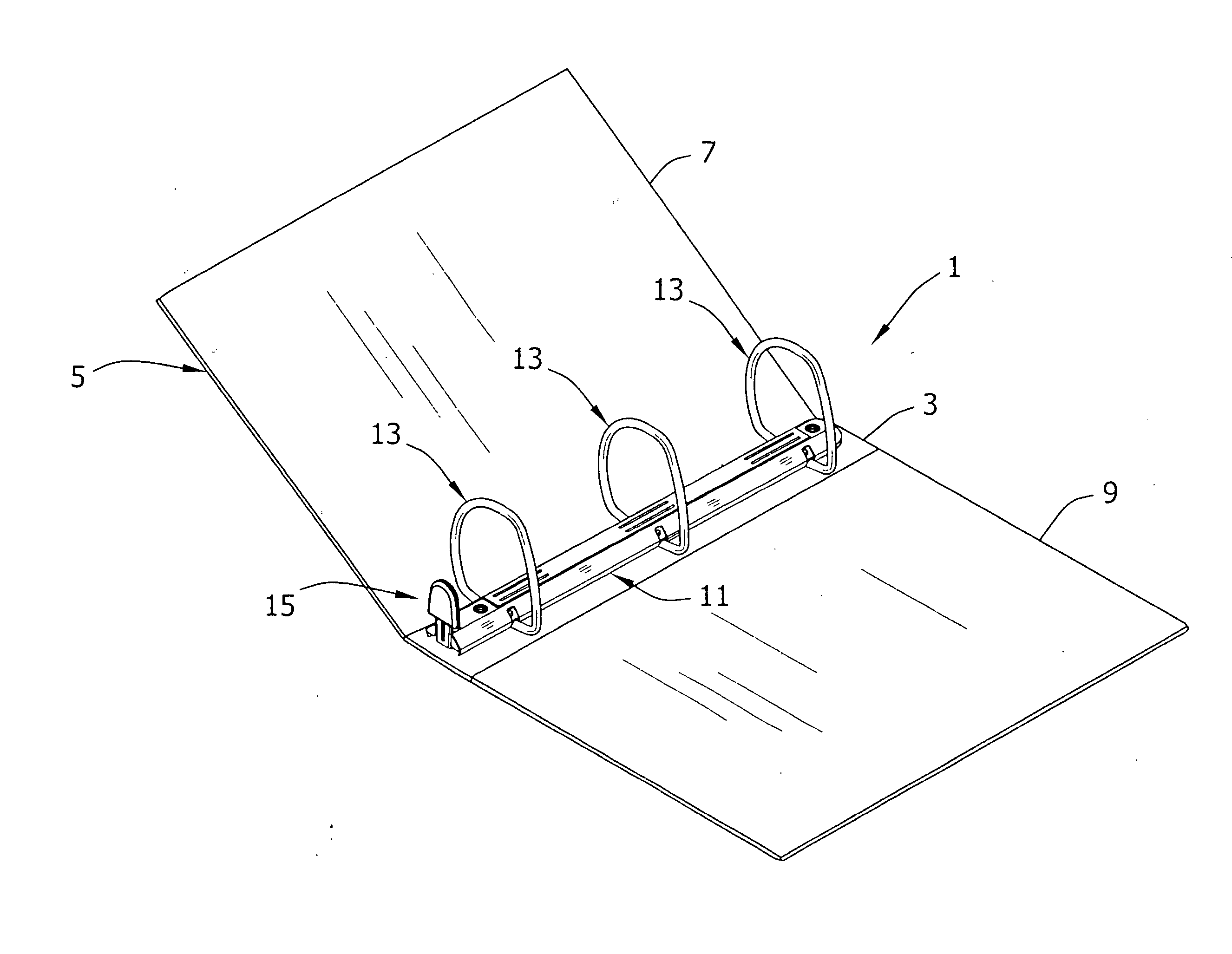
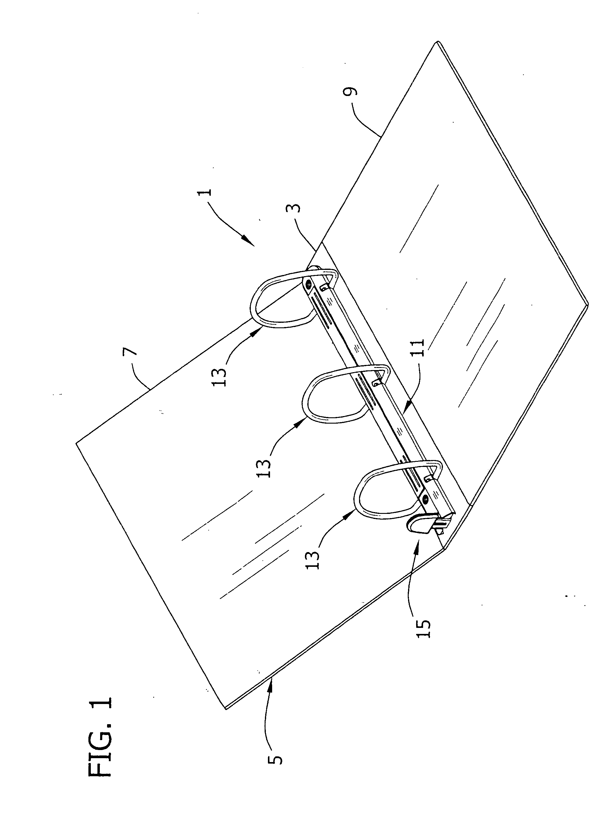
[0037] Referring now to the drawings of the present invention, FIG. 1 shows a first embodiment of a ring binder mechanism of the present invention capable of retaining loose-leaf pages (not shown). The mechanism is generally designated by reference numeral 1 and is shown mounted on a spine 3 of a notebook 5 having a front cover 7 and a back cover 9 hingedly attached to the spine 3. The front and back covers 7, 9 move to selectively cover or expose retained pages. Ring binder mechanisms mounted on surfaces other than a notebook, however, do not depart from the scope of this invention. The mechanism 1 of this embodiment generally includes a hou...


PUM


Abstract

A ring binder mechanism that retains loose-leaf pages and has ring members that do not snap together when they close and that easily open and close as pages accumulate. The mechanism includes a housing that supports two hinge plates for loose pivoting motion, moving the ring members apart or together. The mechanism further includes an actuating lever pivotally mounted on the housing. The lever moves a travel bar and locking elements for controllably pivoting the hinge plates, and therefore controllably moving the ring members apart and together. In particular, the locking elements cam the hinge plates to softly close the ring members. When the ring members are apart, the locking elements register with openings in at least one of the hinge plates. When the ring members are together, the locking elements are out of registration with the openings, blocking the hinge plates from pivoting to separate the ring members.

Description

CROSS-REFERENCE TO RELATED APPLICATION [0001] This application claims the benefit of U.S. Provisional Application No. 60 / 553,155, filed Mar. 15, 2004, the entire text of which is hereby incorporated by reference.BACKGROUND OF THE INVENTION [0002] This invention relates to a ring binder mechanism for retaining loose-leaf pages, and in particular it relates to an improved mechanism for reducing snapping motion of ring members as they close and for securely locking closed ring members together. [0003] As is known in the art, a typical ring binder mechanism retains loose-leaf pages, such as hole-punched papers, in a file or notebook. It generally features multiple rings each including two half ring members capable of selectively opening to add or remove papers, or selectively closing to retain papers and allow them to move along the rings. The ring members mount on two adjacent hinge plates that join together about a pivot axis for pivoting movement within an elongated housing. The hous...

Claims


Application Information

Patent Timeline
IPC IPC(8): B42F13/00B42F13/16
CPCB42F13/26
Inventor CHENG, HUNG YU
Owner WORLD WIDE STATIONARY MFG CO LTD
Why Eureka
Try Eureka