Optical circuit enclosure

Inactive Publication Date: 2006-09-26
TYCO ELECTRONICS RAYCHEM NV
View PDF15 Cites 95 Cited by
  • Summary
  • Abstract
  • Description
  • Claims
  • Application Information

AI Technical Summary

Benefits of technology

[0031]Preferably the laminar element comprises a moisture resistant barrier. This can prevent water and/or moisture ingress into the sealed container. In alternative embodiments the laminar element may not be entirely moisture resistant and in such embodiments the optical components and/or circuit may be enclosed within a moisture resistant sealed envelope with the f

Problems solved by technology

However, known closure and organiser tray arrangements have a number of drawbacks particularly where it is desirable to install expensive and/or delicate optical components since great care must be taken not to damage such components when access to the organiser

Method used


Image

  • Optical circuit enclosure
  • Optical circuit enclosure
  • Optical circuit enclosure

Examples


Embodiment Construction

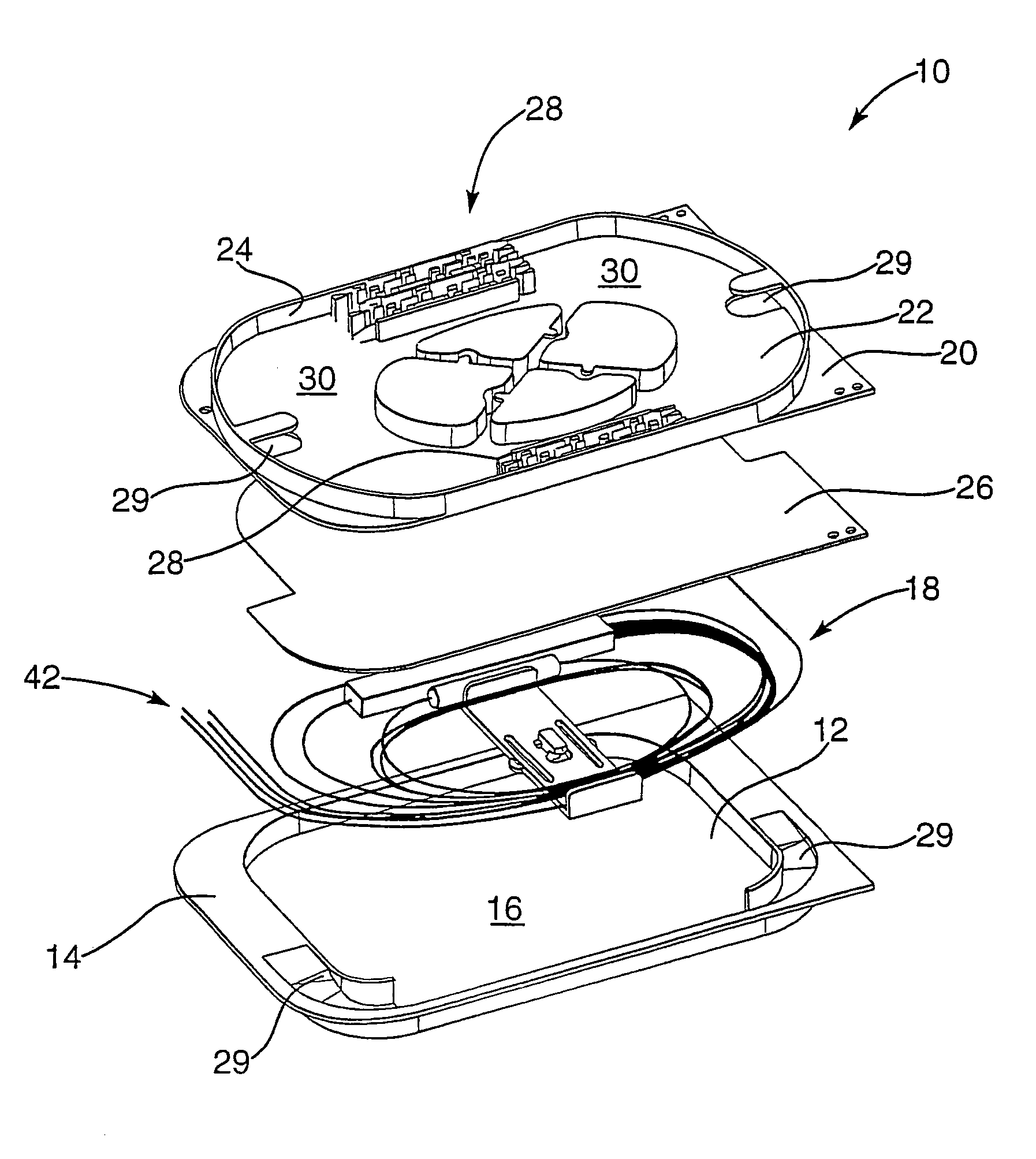
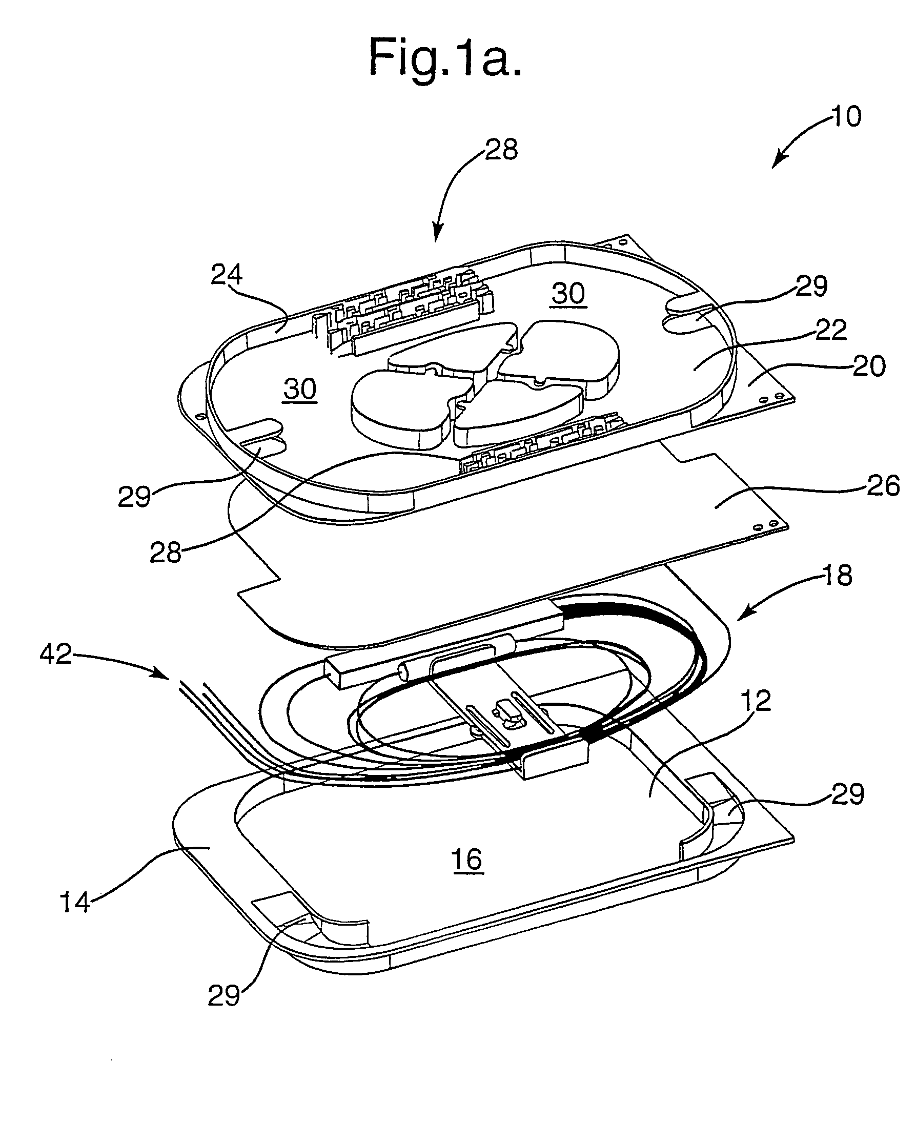
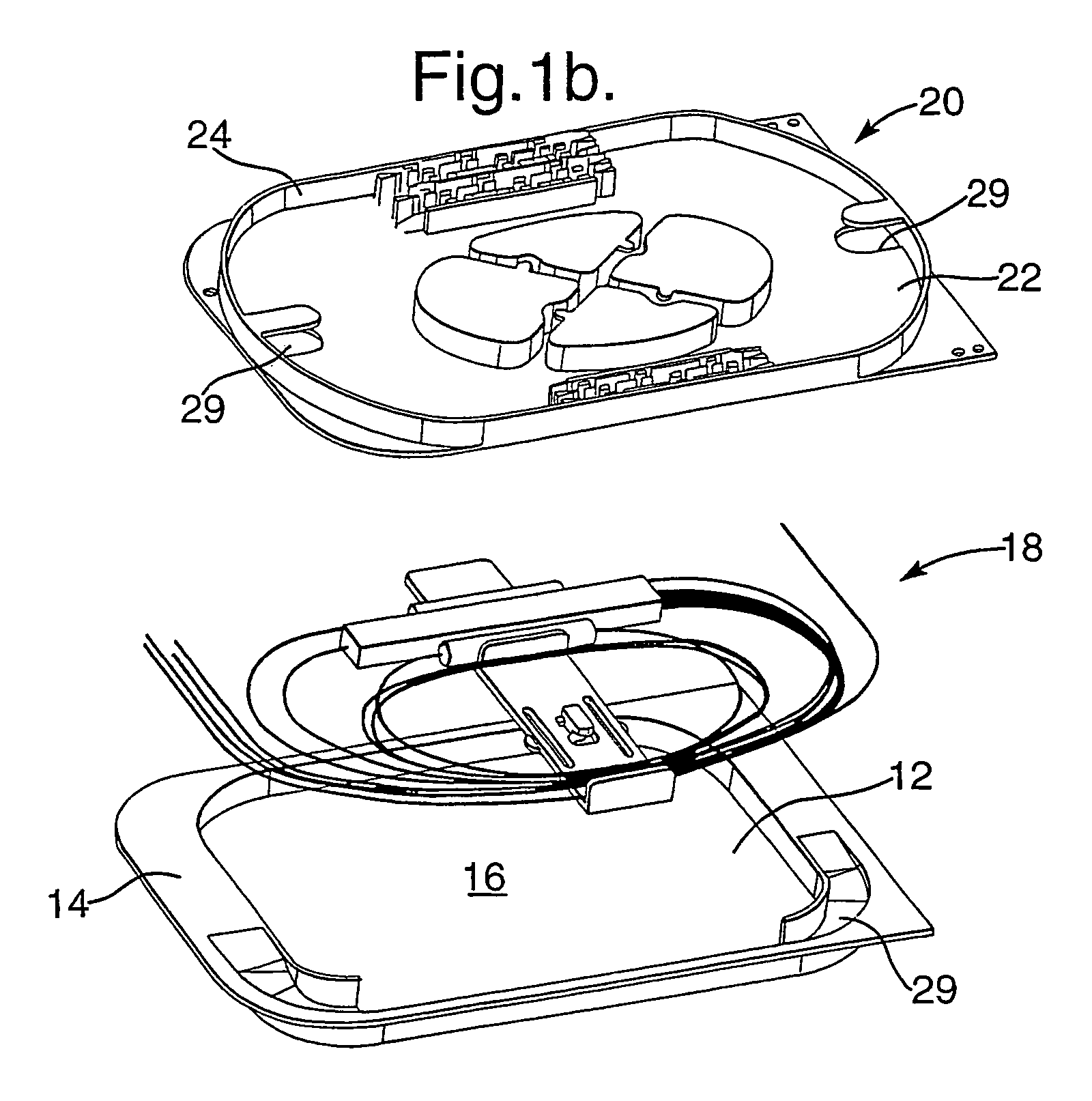
[0048]Referring to FIG. 1a, an optical circuit enclosure 10 comprises a rectangular shaped open container 12 in the form of a shallow rectangular tray type structure having a flat rim 14 surrounding a hollow interior region 16 of the tray. The size and shape of the hollow region 16 is sufficient to accommodate components of a pre-fabricated or pre-assembled optical circuit 18, for example. Various types of optical circuit may be located in the region 16 of the container and may be mounted with respect to the container by various mounting means, for example by snap-fit connections or adhesive etc. In the embodiment of FIG. 1a it is preferred, although not essential, that the optical circuit components 18 are mounted within the region 16 during manufacturing assembly of the enclosure 10.

[0049]The enclosure further comprises a closure member 20 which also may be considered to comprise a rectangular tray type structure having a flat rectangular base 22 and upstanding wall sections 24 wh...


PUM


Abstract

In one aspect the invention provides an optical circuit enclosure enclosing at least one optical circuit or optical circuit component; the enclosure comprises: a tray type container containing at least one optical circuit or optical circuit component; a tray type closure member closing the container; the closure member containing at least one further optical circuit component on an external side thereof for optically connecting the enclosed component to an external optical circuit; and sealing means providing a moisture resistant seal between the container and the closure member.

Description

RELATED APPLICATIONS[0001]The present application is a National Phase application of PCT / GB03 / 001458 filed on Apr. 3, 2003 and published in English, which claims priority from Applications GB 0208568.6 filed on Apr. 12, 2002, GB 0209974.5 filed on May 1, 2002 and GB 0219102.1 filed on Aug. 16, 2002, the disclosures of which are hereby incorporated by reference.FIELD OF INVENTION[0002]This invention concerns an optical circuit enclosure and in particular an enclosure for pre-fabricated pre-installed optical circuits or optical circuit components.BACKGROUND OF THE INVENTION[0003]Fibre optic circuits may contain splitters, filters, attenuators and other passive or active optical components, each of which is normally provided with optical fibres for connecting these components to other components. Optical components can be connected by splicing the ends of the fibre protruding from the components to be joined. For permanent connections it is normally preferred to splice the fibres using...

Claims


Application Information

Patent Timeline
IPC IPC(8): G02B6/00G02B6/44
CPCG02B6/4455G02B6/4454
Inventor BELLEKENS, KATHLEENFRANCKX, JORIS
Owner TYCO ELECTRONICS RAYCHEM NV
Why Eureka
Try Eureka