Junction Cover for Photovoltaic Panel Modules

a technology for photovoltaic panels and junction covers, applied in photovoltaic supports, pv power plants, sustainable buildings, etc., can solve problems such as the inability to remove junction covers

Inactive Publication Date: 2012-01-12
CLEAN ENERGY SOLUTIONS
View PDF1 Cites 18 Cited by
  • Summary
  • Abstract
  • Description
  • Claims
  • Application Information

AI Technical Summary

Benefits of technology

[0005]The present invention is directed to a junction cover for a photovoltaic (PV) panel module system that includes a PV panel mounting structure, a rail, a PV module with a junction box and wiring extending between the rail and the junction box. The junction cover encloses the wiring and includes a base section, a nose section and a pair of feet. The base section includes a plate with first and second side walls extending downwardly therefrom to first and second edges to define an interior with an interior surface. The nose section extends from the base section to an open end and has a top wall, two sides formed by the side walls of the base section and an open side opposite the top wall. The feet are located on either side of the open end of the nose section and extend therefrom. The feet engage the rail to secure the junction cover in place. The base section and / or the nose section can have a plurality of apertures which ventilate the cover and prevent water from collecting in the interior.

Problems solved by technology

When the notches engage the rail and the PV panel is attached to the PV panel mounting structure, the junction cover cannot be removed without detaching the PV panel from the mounting structure.

Method used


Image

  • Junction Cover for Photovoltaic Panel Modules
  • Junction Cover for Photovoltaic Panel Modules
  • Junction Cover for Photovoltaic Panel Modules

Examples


first embodiment

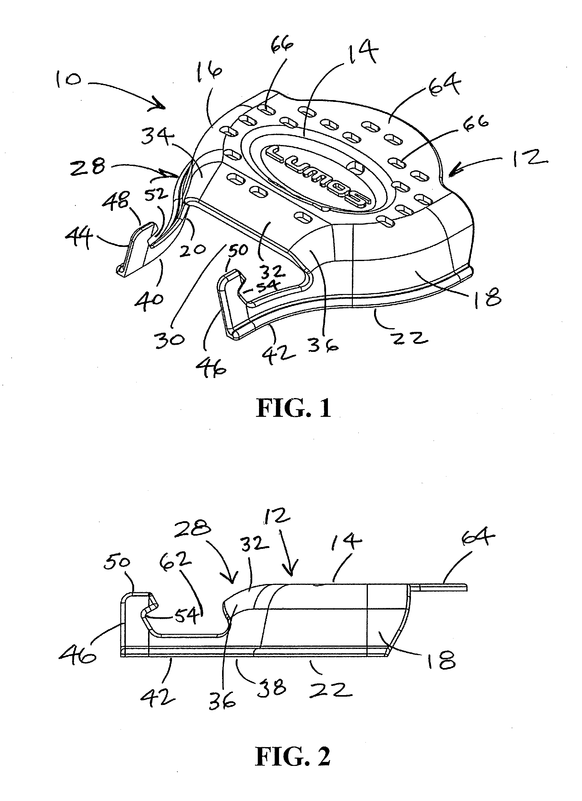
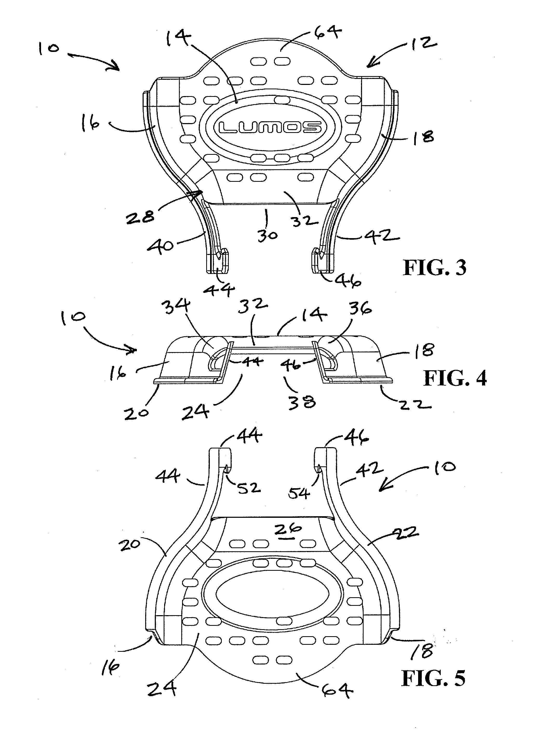
[0038]The junction covers of the present invention will now be described in terms of the drawings. FIGS. 1-14 show the junction cover 10 and FIGS. 1-5 show the junction cover 10 having a base section 12 formed by a plate 14 with first and second side walls 16, 18 extending downwardly therefrom to a pair of edges 20, 22 to define an interior 24 with an interior surface 26. The junction cover 10 also includes a nose section 28 extending from the base section 12 to an open end 30. The nose section 28 has a top wall 32, two sides 34, 36 formed by the side walls 16, 18 of the base section 12 and an open side 38 opposite the top wall 32. A pair of feet 40, 42 extends from either side of the open end 30 of the nose section 28. The feet 40, 42 engage the rail 84 (FIGS. 10 and 14) to secure the junction cover 10 in place. A member 44, 46 extends upwardly from each of the feet 40, 42 to a distal end 48, 50. The members 44, 46 have notches 52, 54 near the distal ends 48, 50 on the side 56, 58 ...

second embodiment

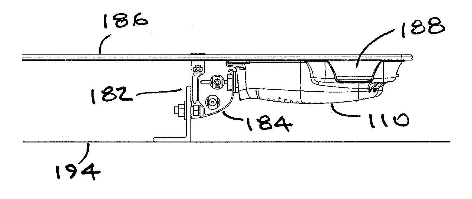
[0043]FIGS. 15-21 show the junction cover 110 and FIGS. 15-18 show the junction cover 110 having a base section 112 formed by a plate 114 with first and second side walls 116, 118 extending downwardly therefrom to a pair of edges 120, 122 to define an interior 124 with an interior surface 126. The junction cover 110 also includes a nose section 128 extending from the base section 112 to an open end 130. The nose section 128 has a top wall 132, two sides 134, 136 formed by the side walls 116, 118 of the base section 112 and an open side 138 opposite the top wall 132. A pair of feet 140, 142 extends from either side of the open end 130 of the nose section 128. The feet 140, 142 engage the rail 184 (FIGS. 19 and 21) to secure the junction cover 110 in place.

[0044]The base section 112 can also have four flexible legs 144, 146, 148, 150 extending from the side walls 116, 118. The legs 144, 146, 148, 150 can further define the interior 124 and form part of the interior surface 126. One or...


PUM


Abstract

A junction cover for a photovoltaic (PV) panel module system that includes a PV panel mounting structure, a rail, a PV module with a junction box and wiring extending between the rail and the junction box. The junction cover encloses the wiring and includes a base section, a nose section and a pair of feet. The base section includes a plate with first and second side walls extending downwardly therefrom to first and second edges to define an interior with an interior surface. The nose section extends from the base section to an open end and has a top wall, two sides formed by the side walls of the base section and an open side. The feet are located on either side of the open end of the nose section and extend therefrom. The feet engage the rail to secure the junction cover in place to enclose the junction box and wiring.

Description

[0001]This application claims priority from provisional application Ser. No. 61 / 363,544, filed on Jul. 12, 2010, which claims priority to application Ser. No. 12 / 743,476, filed on Mar. 12, 2010, which claims priority to provisional application Nos. 61 / 159,677, filed Mar. 12, 2009 and 61 / 254,974, filed Oct. 26, 2009, all of which are hereby incorporated by reference herein in their entirety for all purposes.FIELD OF INVENTION[0002]The present invention relates to a junction cover, a system that includes a junction cover and a method for covering wiring at junctions between electrical junction boxes for photovoltaic panel modules and wiring conduits, wireways and / or raceways.BACKGROUND OF THE INVENTION[0003]Photovoltaic (“PV”) panels, also known as solar panels, are well known in the art for converting solar energy into electrical energy. As used herein, the term photovoltaic refers to the generation of a voltage when radiant energy falls on the boundary between dissimilar substances,...

Claims


Application Information

Patent Timeline
Patent Type & Authority Applications(United States)
IPC IPC(8): H01L31/0203
CPCH01L31/05Y02E10/50Y02B10/12H02S40/36H02S40/34H01L31/0482H01L31/0485H02S20/23Y02B10/10
Inventor KLINGA, CHRISTOPHER STEPHENFRANKLIN, SCOTT
Owner CLEAN ENERGY SOLUTIONS
Why Eureka
Try Eureka