Self-ligating bracket for use in orthodontics

Active Publication Date: 2008-05-15
BERNHARD FOERSTER GMBH 75172 PFORZHEIM DE
View PDF10 Cites 85 Cited by
  • Summary
  • Abstract
  • Description
  • Claims
  • Application Information

AI Technical Summary

Benefits of technology

[0005]Now, it is the object of the present invention to provide a self-ligating bracket for use in orthodontics where the slot of the bracket can be closed by a slide which as such need not be resilient, which may have a mechanically stable design, which is u

Problems solved by technology

Overcoming the two elements is difficult because the slide is displaced at a right angle relative to the direction in which the spring has to be urged back into the bore.
Further, there is a risk that the spring and the slide may get mechanically stuck one relative to the other or that the spring may be damaged.
In view of the small dimensions brackets normally have the known bracket is difficult to realize.
The slide is not secured in the open position so that it may get lost, which may have especially disagreeable consequences when it happens in a person's mouth because then

Method used


Image

  • Self-ligating bracket for use in orthodontics
  • Self-ligating bracket for use in orthodontics
  • Self-ligating bracket for use in orthodontics

Examples


Embodiment Construction

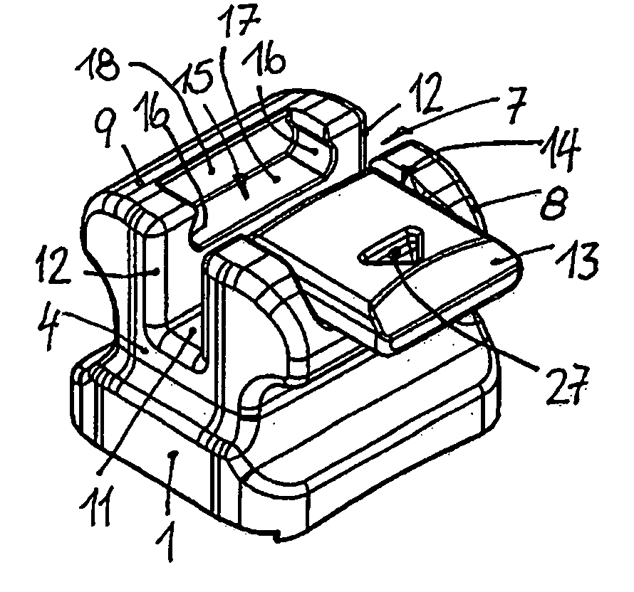
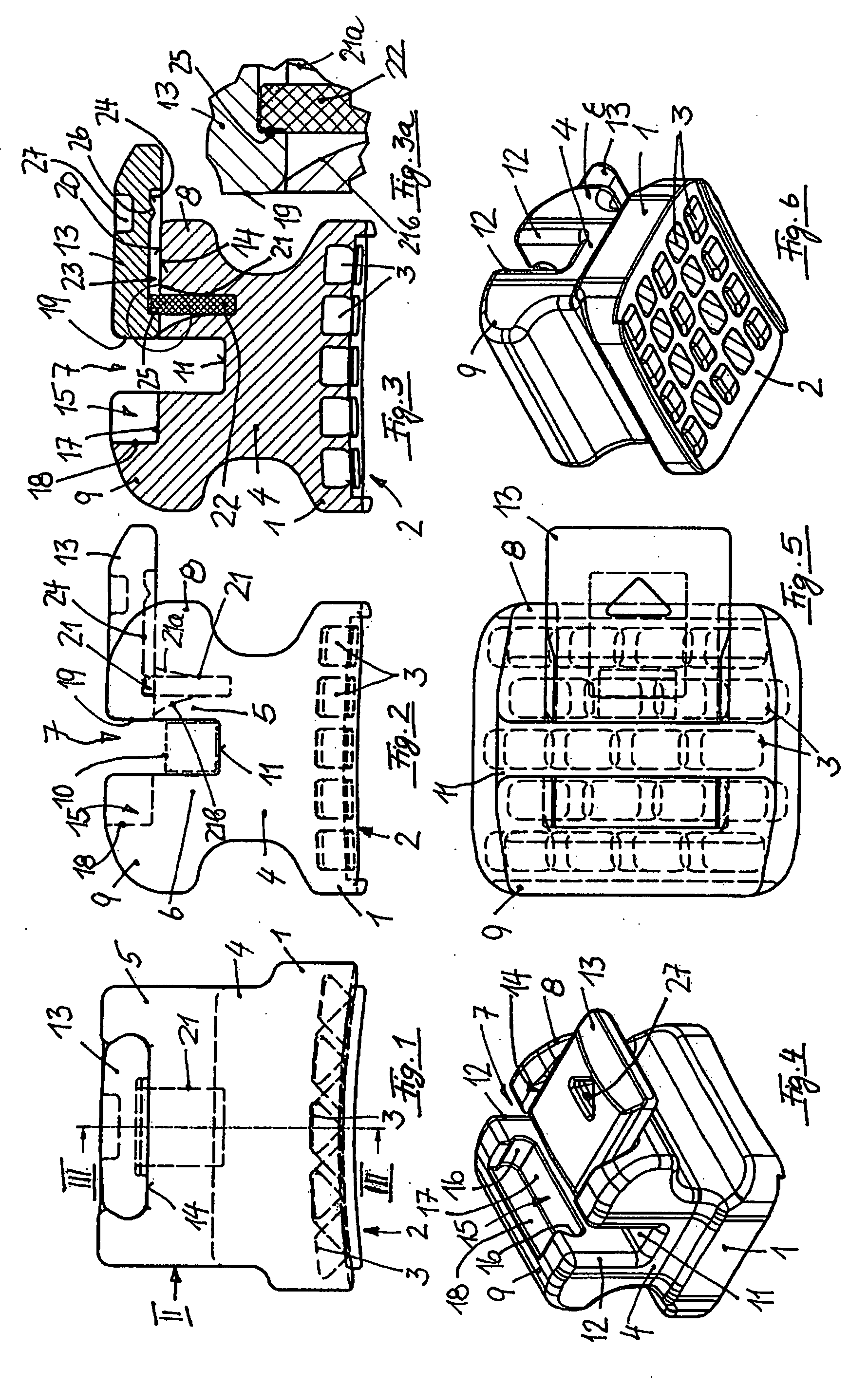
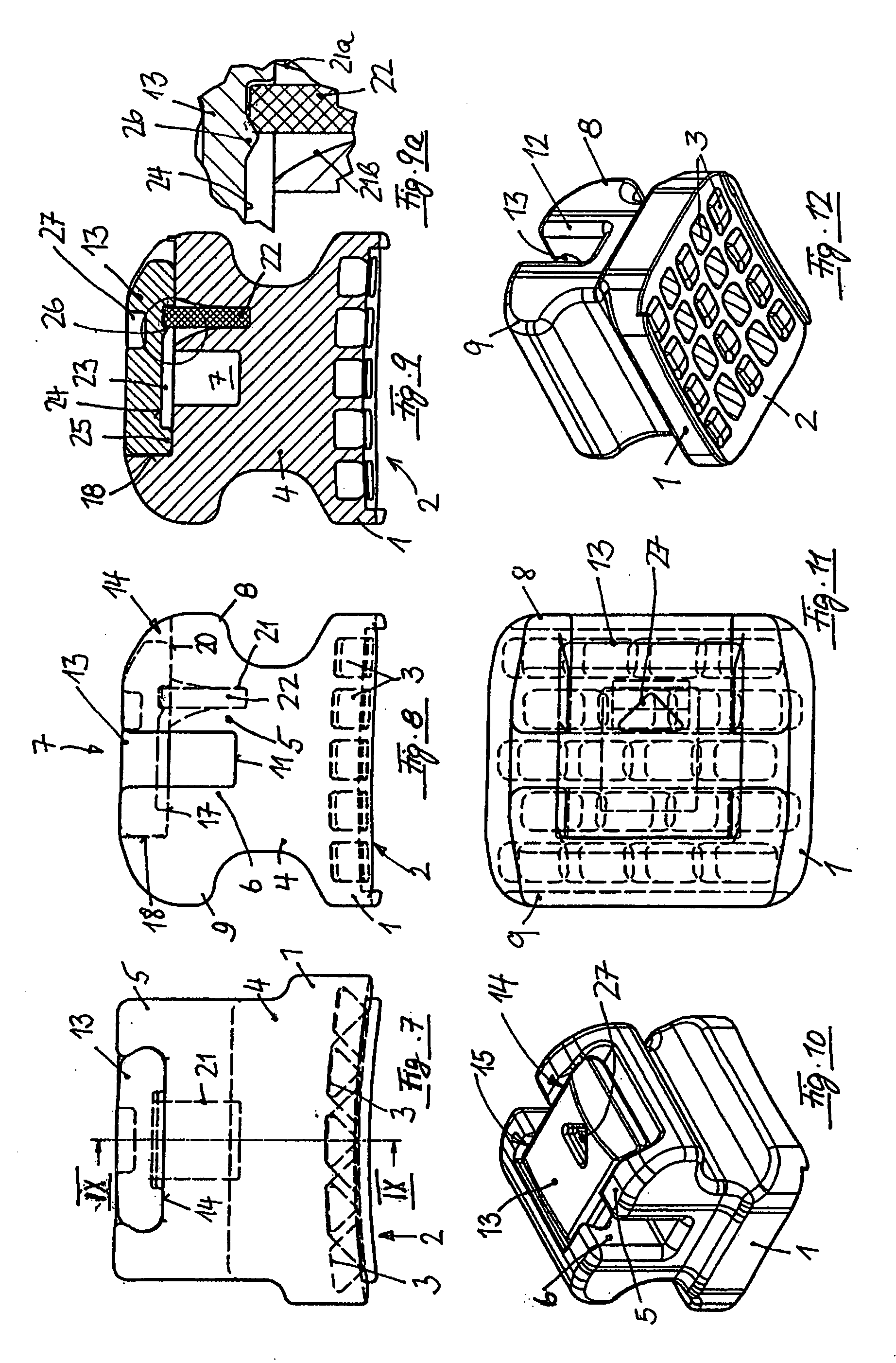
[0049]The bracket illustrated in FIGS. 1 to 12 has a curved base 1 the curvature of which is approximated to the front of a tooth. The bottom surface 2 of the base 1, forming the lingual side of the bracket, is provided with recesses 3 of undercut shape, arranged in a row. The recesses 3 have a rectangular contour, in the cross-section shown in FIG. 3. In a cross-section normal to that cross-section, the recesses 3 have a rhombic contour, as illustrated in FIG. 1. In order to glue the bracket onto a front of a tooth, an adhesive may be applied on the bottom surface 2. The interaction between the undercut recesses 3 and the adhesive provides good bonding strength. The recesses 3 and, together with them, the undercuts are orientated identically in each row. Between the rows they are, however, alternately oriented in one and the other direction. This has the effect that when thrust is applied on the bracket in the mesial-to distal direction the same bonding strength will be achieved as...


PUM


Abstract

The self-ligating bracket for use in orthodontics comprises
a base; an occlusal wall and a gingival wall extending from the base and having at least one ligature wing; a slot separating the occlusal wall and the gingival wall; a slide retained in a guide provided in the occlusal and/or gingival wall and arranged for being displaced between a closed position, in which the slide bridges the slot, and an open position in which the slot is open in the labial direction; means capable of retaining the slide in both its closed and open position; at least one recess in which a spring is seated and which is arranged in the gingival or occlusal wall of the bracket and is provided with an opening that faces the slide and from which a spring projects; a first stop on the slide which abuts against the at least one spring in the open position of the slide; a projection is which provided on the slide and which is so arranged that during displacement of the slide to its closed position it will abut against the spring before it reaches its closed position; space on both sides of the projection which accommodates the spring that projects from the recess which expands toward its opening facing the slide so that the spring can bent in the two directions of displacement of the slide; a second stop that abuts the slide in its closed position, once its projection has overcome the at least one spring.

Description

[0001]The present invention relates to a self-ligating bracket for use in orthodontics which comprises a base, an occlusal wall extending from the base and having at least one occlusal ligature wing, a gingival wall extending from the base and having at least one gingival ligature wing, a slot separating the occlusal wall and the gingival wall one from the other and extending continuously in the mesial-to-distal direction, and a slide which is retained in a guide provided in the occlusal wall and / or in the gingival wall and which is arranged for being displaced in the guide in the gingival-to-occlusal direction, between a closed position in which the slide bridges the slot and an open position in which the slot is open in the labial direction; and means capable of retaining the slide in both its closed position and in its open position. A bracket of that kind has been known from U.S. Pat. No. 5,322,435 A. For closing its slot, the known bracket comprises a slide arranged for being d...

Claims


Application Information

Patent Timeline
IPC IPC(8): A61C7/14
CPCA61C7/287
Inventor FORSTER, ROLF
Owner BERNHARD FOERSTER GMBH 75172 PFORZHEIM DE
Why Eureka
Try Eureka