Flashing adaptable to different shapes of roof

a technology of flashing and roof, applied in the field of flashing, can solve the problems of difficult or even impossible installation of flashings, installation of flat base of pitched flashings over apertures made in tiled roofs, and installation of flat base of pitched flashings over apertures that do not have flashings, etc., to achieve efficient and versatile, easy and efficient manner

Inactive Publication Date: 2005-09-22
SICK +1
View PDF41 Cites 15 Cited by
  • Summary
  • Abstract
  • Description
  • Claims
  • Application Information

AI Technical Summary

Benefits of technology

[0014] Thanks to its particular structure, the flashing according to the invention may be installed in a very easy and efficient manner on any kind of shape of roofs, including roofs with different tile configurations.
[0015] In all cases, the installation problems mentioned hereinabove are solved. The flashing according to the invention can be prefabricated in a manufacturing environment rather than be built on site prior to installation. Thus, the flashing according to the invention is very efficient and versatile and can be used in an efficient way on any kind of shape of roof or tile thereon.

Problems solved by technology

However, due to the different profiles and overall shapes of-various roofing components such as tiles used on roofs, current factory-built flashings do not provide adequate sealing of the gap between the vertical member and the roof and, in several cases of tiled roofs, flashings are difficult or even impossible to install.
Unfortunately, most pre-fabricated chimney installers are not familiar with this practice.
Consequently, installation of the flat base of a pitched flashing positioned over an aperture made in a tiled roof and fastening of the flashing on a roof that does not have a generally flat surface becomes problematic.
Unfortunately, the use of rubber or silicone is not advisable when the flashing is used to seal the gap between a chimney and a roof, due to the high temperatures that may be attained at the outer surface of the chimney.
Certification of the use of such flashings with chimneys is therefore complicated due to the choice of materials.

Method used


Image

  • Flashing adaptable to different shapes of roof
  • Flashing adaptable to different shapes of roof
  • Flashing adaptable to different shapes of roof

Examples


Embodiment Construction

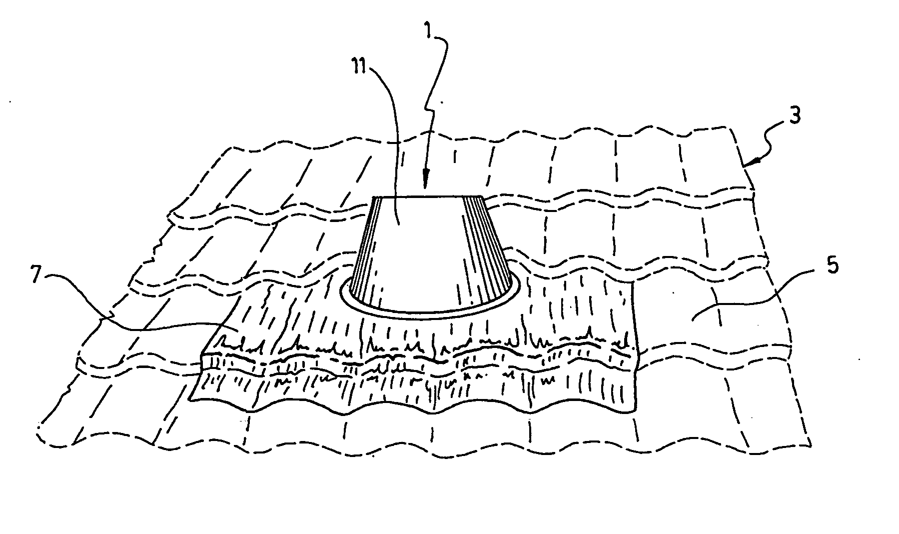
[0026] As aforesaid and shown in FIGS. 1 to 3, the flashing 1 according to the invention is intended to be used for weatherproofing the gaps that exist in-between a roof 3 and a chimney passing therethrough (or alternatively a pipe, a venting duct or any other kind of member having to pass through the roof). More particularly, the flashing 1 according to the present invention can be installed on different shapes of roof or tiles 5 thereon.

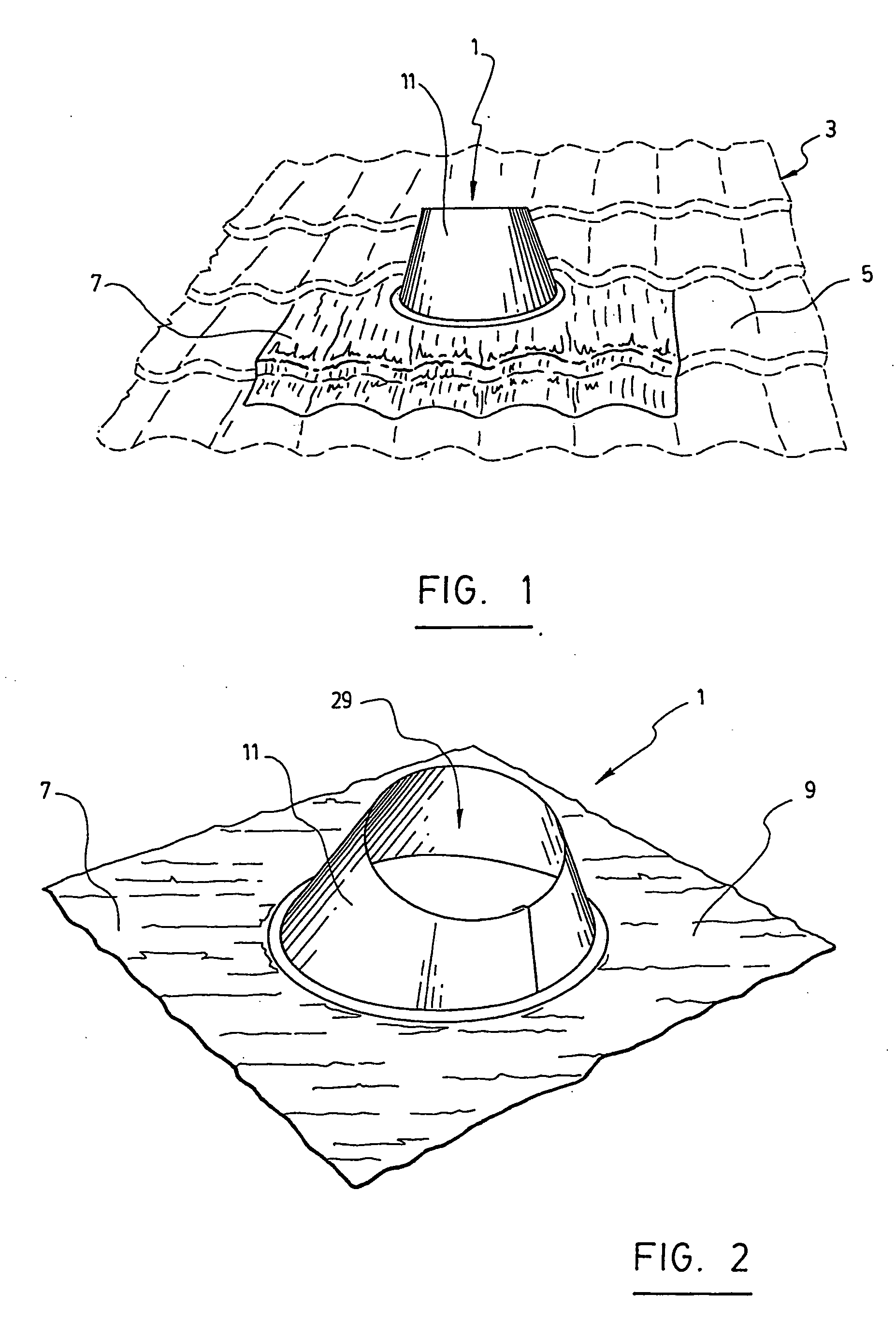
[0027] As shown in FIG. 2, the flashing 1 comprises a base member 7 adapted to be mounted over an aperture made in the roof 3 to allow passage of a chimney. The flashing 1 also comprises a surrounding member 11 extending upwardly from the base member 7 to fit around the chimney.

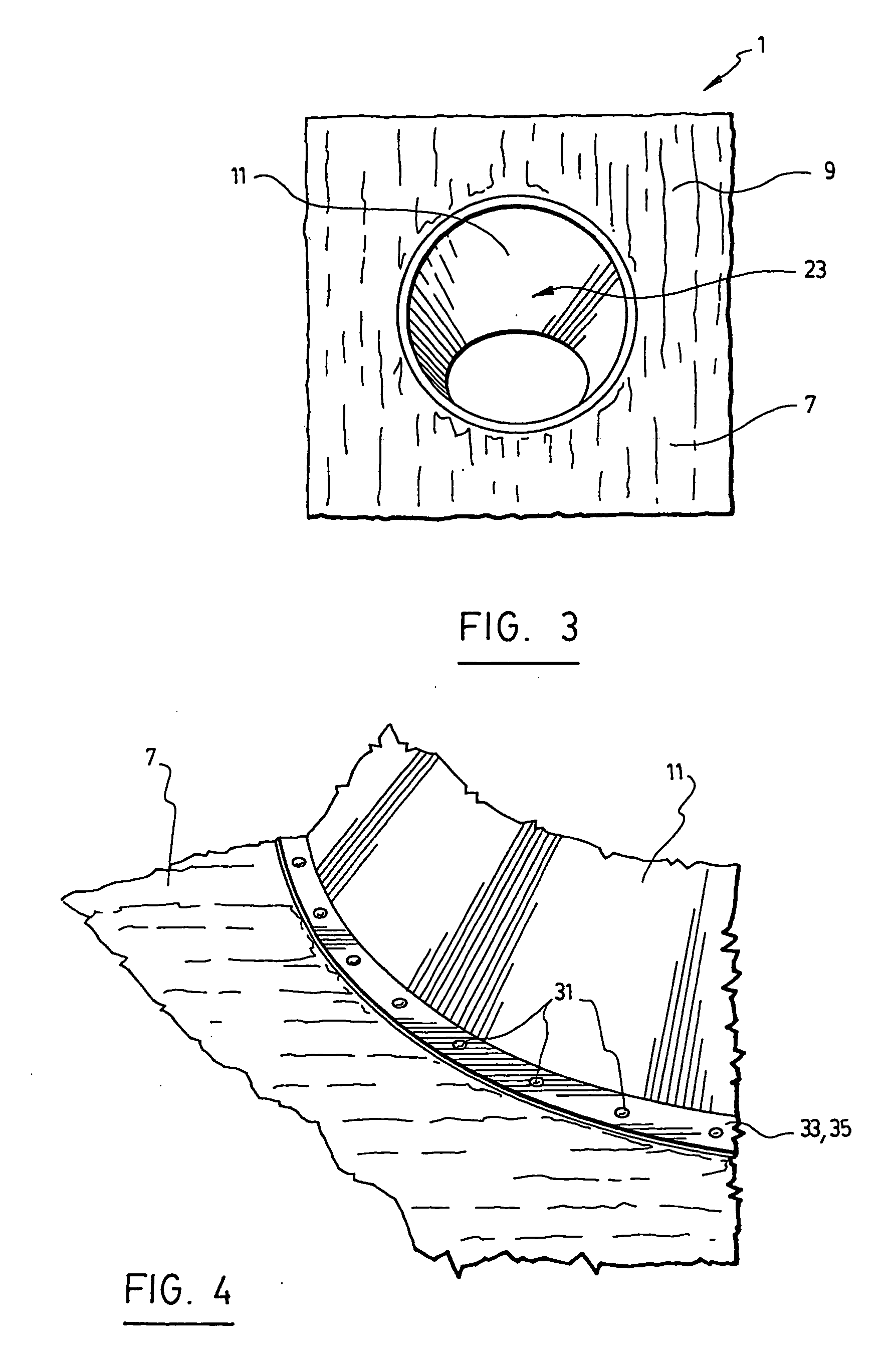
[0028] As shown in FIG. 3, the base member 7 comprises a panel 9 of generally quadrilateral shape. The panel 9 is provided with an opening 23 large enough to allow passage of the chimney therethrough.

[0029] In accordance with a further preferred aspect, the base member 7 ...


PUM


Abstract

Disclosed is a flashing for weatherproofing an aperture made in a roof to allow passage of a chimney through the roof. The flashing has a malleable base member adapted to be mounted over the aperture made in the roof and on a surface of the roof surrounding the aperture and to match the shape of roof surface. The base member comprises a panel having edges adapted to be positioned on the roof and an opening large enough to allow passage of the chimney therethrough. The flashing also comprises a surrounding member being tubular in shape and extending upwardly from the base member to fit around the chimney. The bottom and surrounding structures are linked through a joining ring structure encircling a bottom opening of the surrounding member.

Description

FIELD OF THE INVENTION [0001] The present invention relates to a flashing useful for weatherproofing an aperture made in a roof. More particularly, it relates to a flashing adapted for use on a roof having different shapes. BACKGROUND OF THE INVENTION [0002] It is of common practice in the construction industry to use a flashing to seal the interstitial gap between the roof and a vertical member such as a pipe, a venting duct or a chimney passing through an aperture made in the roof. In addition to ensuring weatherproofing of the roof aperture, the flashing is usually also devised to ensure proper drainage of the water that can accumulate on the roof. [0003] However, due to the different profiles and overall shapes of-various roofing components such as tiles used on roofs, current factory-built flashings do not provide adequate sealing of the gap between the vertical member and the roof and, in several cases of tiled roofs, flashings are difficult or even impossible to install. [000...

Claims


Application Information

Patent Timeline
Patent Type & Authority Applications(United States)
IPC IPC(8): E04D1/36E04D3/38E04D13/14E04D13/147E04D15/00E04G23/00
CPCE04D13/1476
Inventor BIBAUD, ANDREPELLETIER, MARIO
Owner SICK
Why Eureka
Try Eureka